
Motors generate a regenerative voltage spike when they slow down or stop quickly, and that spike can damage a motor controller. This guide covers the main ways to protect a controller: a bypass diode, a voltage clamp, a pre-charge resistor, and the controller’s maximum voltage setting.
When using a RoboClaw or MCP motor controller, several precautions help prevent damage to the controller. Most relate to the regenerative voltage that motors generate when they are slowed down or stopped quickly. This voltage spike comes on suddenly and can be high enough to easily damage a controller. The methods below each protect against it in a different way.
How Does a Bypass Diode Protect the Controller?
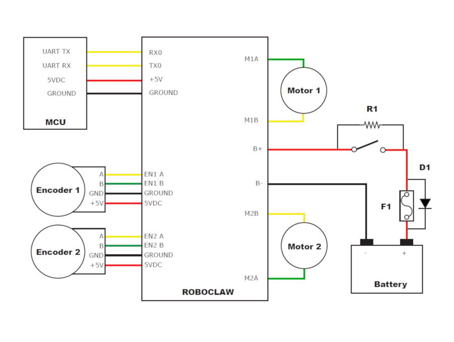
A bypass diode gives the motor’s regenerative energy a safe return path to the battery. It is wired in parallel with the switch or fuse on the positive lead of the battery. Under normal operation the diode does nothing, because it is oriented so that it does not conduct across the fuse. If the fuse blows, however, the regenerative energy from the motors still needs somewhere to go, and the diode provides that path back to the battery’s positive terminal instead of forcing the spike onto the controller.
Orient the diode with its cathode toward the battery and its anode toward the controller, so it conducts from the controller back to the battery only when needed. This protection method applies only when using a battery as the power source, since only a battery will tolerate the returned current. Using it with a linear or switching power supply is likely to damage the supply. A power diode rated for 1 to 3 amps of continuous current is suitable for most scenarios. When using a bypass diode, it is not necessary to also use a voltage clamping circuit.
How Does a Voltage Clamp Protect the Controller?
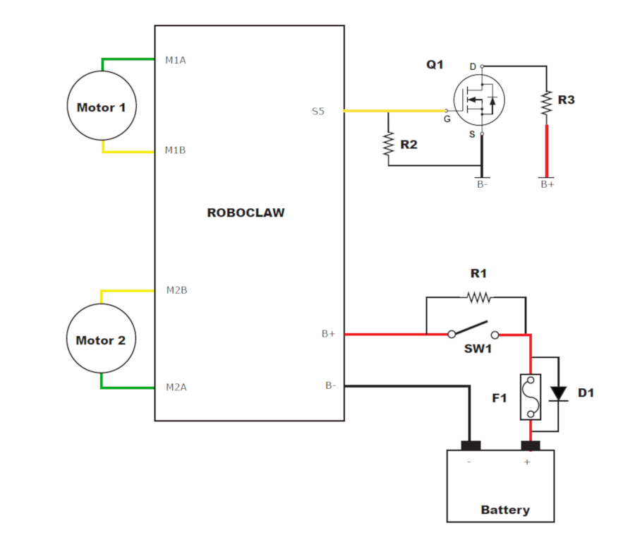
A voltage clamp is another way to shunt large regenerative voltage spikes away from the motor controller. It uses a MOSFET, a voltage-controlled switch, that is turned on by a signal from the controller. Once the MOSFET turns on, the excess energy is sent through a low-resistance power resistor that converts it to heat. This is the protection method to use when powering a RoboClaw or MCP controller from a linear or switching power supply.
The current recommended MOSFET is DigiKey part number BUK965R8, which is a surface-mount package. If it is unavailable, or you want a through-hole part that is easier to hand-solder, the IRL540N (100V, 36A, TO-220) is a logic-level alternative stocked in single quantities, suited to lighter clamp loads. In the diagram below, Q1 is the MOSFET, R3 is the power resistor, and R2 keeps the MOSFET turned off when no signal is applied to its gate. When using a voltage clamping circuit, it is not necessary to also use a bypass diode. For a full walkthrough of wiring and configuring a clamp, see Using a Voltage Clamp with RoboClaw.
Why Use a Pre-Charge Resistor?
The RoboClaw and MCP controllers each contain a bank of onboard capacitors. When power is first applied, these capacitors charge rapidly, which causes a large inrush of current into the controller that can cause damage. A pre-charge resistor prevents this by wiring a suitably sized resistor in parallel across the switch on the positive lead of the power supply. The resistor lets the board charge its capacitors slowly before the main power is switched on, so the inrush current is limited.
Note that a resistor wired in parallel with the switch will draw power the entire time power is connected, which is fine for systems where the power source is disconnected after use. For a permanently connected power source, add a switch in series with the resistor so the pre-charge circuit can be turned on and off. In that configuration, remember to turn the pre-charge switch on first, wait a short moment, and then switch on the main power.
A pre-charge resistor is mainly needed on the larger controllers, which have the biggest onboard capacitor banks and draw the most inrush current when powered on. On the smaller models, roughly the 2x7A through 2x45A, the inrush is small enough that a pre-charge resistor generally is not necessary. It is most worth adding on the larger boards, and especially at system voltages of 24 volts and above.
To find the resistor value, divide the desired charging time by 3, then divide the result by the capacitance of the board’s capacitor bank in farads. Rounding up to the nearest standard resistor value is fine, and a 1/4 watt resistor is adequate. Below is a calculation for a RoboClaw 2x15A with a 1 second charging time:
Charging time:     1 second
Board capacitance: 400uF = 0.0004 farads

R = (charging time / 3) / capacitance
R = (1 / 3) / 0.0004
R = 833 ohms
The value can be rounded up to 1000 ohms (1 kΩ), which is a commonly available resistor.
The capacitor bank values for the larger controllers are listed below:
| Board | Capacitance |
|---|---|
| 2x60A | 1080µF |
| Solo 60A | 400µF |
| MCP263 / MCP266 | 400µF |
| 2x200A | 2820µF |
How Does the Maximum Voltage Setting Help?
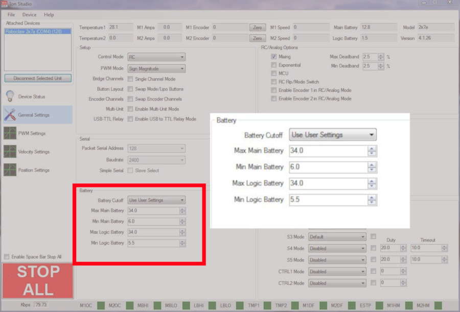
The final protection is to properly set the maximum voltage for the main battery. When the maximum voltage is exceeded by 1V, the motor controller brakes both motor channels. This setting does not protect the power supply from regenerative voltage, so it is recommended to use a voltage clamp alongside it when running from a power supply. The maximum main battery voltage is set in Motion Studio; see Configuring RoboClaw Battery Settings to learn more. The general recommendation is to set the maximum main battery voltage 1 to 2 volts above the maximum voltage of the power source in use.
Next Steps
Combined, these methods keep a motor controller safe from regenerative spikes and inrush current. To go deeper on the two that need their own setup:
- Using a Voltage Clamp with RoboClaw, for wiring and configuring a clamp step by step.
- Configuring RoboClaw Battery Settings, for setting the maximum battery voltage.


