A voltage clamp protects a motor controller and its power supply from the regenerative voltage spike created when a motor is stopped or slowed quickly. This guide shows how to wire and configure a voltage clamp with a RoboClaw, using either the BasicMicro VClamp board or a discrete MOSFET circuit.
Why Use a Voltage Clamp?
A voltage clamp is a circuit used with a motor controller to divert excess energy away from the control circuitry and power supply to prevent damage. In both applications discussed below, a MOSFET acts as a switch that diverts excess power through a power resistor, where it is dissipated as heat. The RoboClaw and MCP motor controllers can both trigger this type of external circuit when a user-programmable voltage is reached.
The primary purpose of a voltage clamp is to protect a motor controller’s power supply from the regenerative energy created when a motor is stopped or slowed down quickly. A motor spins when power is applied to it, but it also acts as a generator when it slows down or is suddenly stopped. During that moment the motor pushes current back into the motor controller and power source, which drives the supply voltage up. Switching power supplies are not designed to absorb this returned energy, and some batteries will not tolerate the sudden inrush of current either. A voltage clamp detects the resulting rise in voltage and sends the excess current to a resistor, where it is turned into heat.
Using the VClamp Board
- To start, the RoboClaw motor controller should be fully wired to power and an appropriate motor. An example of doing so can be found in RoboClaw RC Controlled Differential Drive Setup, by following it up to step 10.
- Begin wiring the voltage clamp board at the control header on the board. Use the table below to connect the voltage clamp board to the RoboClaw.
Function VClamp Board RoboClaw 5V Power 5+ terminal Any 5V pin Ground GND terminal Any ground pin Control Signal CTRL terminal S3, S4, or S5 pin (selectable in Motion Studio) - Select the resistor for the voltage clamp based on the table below. The DigiKey parts listed are all 50 watt resistors, which are sufficient for most use cases. If the voltage clamp is expected to be on for long periods, or the motor is driving a large load, a resistor with a higher power rating may be necessary.
Designator Part Resistance 12VDC 24VDC 36VDC 48VDC 60VDC R1 KAL50FB1R00 1 Ohm 12A 24A 36A 48A 60A R1 KAL50FB2R00 2 Ohm 6A 12A 18A 24A 30A R1 KAL50FB3R00 3 Ohm X 6A 9A 12A 15A R1 KAL50FB5R00 5 Ohm X X 7.2A 9.6A 12A - Wire the power supply to the voltage clamp board, noting polarity. The positive side connects to the “B+” terminal and the negative side connects to the “GND” terminal.
- Wire the resistor to the voltage clamp board by attaching it to the “R1-A” and “R1-B” terminals. The resistor can be wired in either direction.
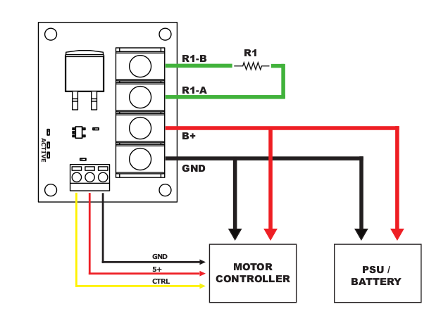
Figure 1: The completed wiring for the voltage clamp board. - Apply power to the RoboClaw and connect it to a computer running Motion Studio with a USB cable. Connect to the RoboClaw by clicking “Connect Selected Unit,” then click “General Settings” on the left-hand side to open the configuration windows. In the “Battery” pane, select “Use User Settings” from the dropdown and set “Max Main Battery” (1) to 1-2 volts above the “Main Battery” voltage shown in the upper right-hand corner. Then, in the “I/O” pane, locate the setting labeled “S3 Mode” (2), “S4 Mode,” or “S5 Mode,” depending on which pin the control wire connects to. Select “Voltage Clamp” from the dropdown for that pin, and check the “Invert” box for the selected pin.
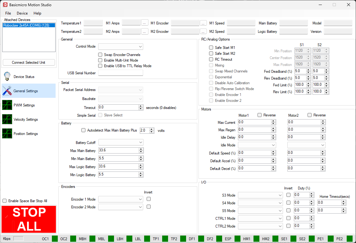
Figure 2: The Max Main Battery setting (1) and the S3 Mode setting (2) in Motion Studio’s General Settings.
- Finally, test the voltage clamp to make sure it works properly. First, confirm that the voltage clamp is off when no motors are moving.
- Open Motion Studio and click “PWM Settings” on the left-hand side. Using the slider for the appropriate motor channel, start a motor spinning and then slow it down or stop it rapidly. When the voltage rises 1V above the limit set in the battery settings, the voltage clamp should turn on. An LED on the voltage clamp board lights up when the clamp is active. The clamp should turn back off once the voltage returns to the maximum voltage setting; the 1V difference between the trigger and release points is the clamp’s hysteresis.
- Test the system again to make sure an excessive voltage is not still occurring. Watch the voltage reading in Motion Studio, or use the graphing feature covered in Graphing in Motion Studio. If an excessive voltage spike is still occurring, substitute a lower-resistance resistor and repeat until the voltage clamp works as it should.
- Lastly, check that the resistor is not becoming excessively hot. If it is, swap in a physically larger resistor or one with a higher power rating.
To improve the performance of the voltage clamp, mount the resistor to a metal surface to help cool it.
Voltage Clamp Without the VClamp Board
- As with the voltage clamp board, the motor controller should already be wired for power and connected to a motor.
- Without the voltage clamp board, all of the components of the voltage clamp circuit have to be wired and soldered together. Use the diagram below as a reference when building the circuit. Q1 is the MOSFET; the current recommendation is DigiKey part number BUK965R8, which is a surface-mount package. If it is unavailable, or you want a through-hole part that is easier to hand-solder, the IRL540N (100V, 36A, TO-220) is a logic-level alternative stocked in single quantities, suited to lighter clamp loads. R2 is a resistor that keeps the MOSFET off when it is not in use; a 10 kohm resistor should be used for R2. R3 is the power resistor that dissipates the energy and should be sized according to the resistor table in the previous section.
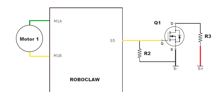
Figure 3: The wiring diagram for using a discrete MOSFET. - Configuring the voltage clamp in Motion Studio is the same as in the previous section, setting “Max Main Battery” (1) and the mode for the chosen I/O pin (2), with one exception: do not set the “Invert” option for the chosen pin.
Figure 4: The Max Main Battery setting (1) and the S3 Mode setting (2), configured the same way for a discrete MOSFET.
- Test the finished voltage clamp circuit the same way as in the previous section.
To improve the performance of the voltage clamp, mount the resistor to a metal surface to help cool it.
Next Steps
With the voltage clamp configured, your RoboClaw and power supply are protected against regenerative voltage spikes. To learn more about setup and protection:
- Motor Controller Protection: Diodes, Clamps, and Pre-Charge Resistors, for other ways to protect your controller.
- Graphing in Motion Studio, for watching voltage and current in real time.


