The RoboClaw Solo ships in a protective case and is not sold as a bare board, but many customers remove the case to save space or weight in tight builds. This guide covers mounting the bare board safely, wiring a motor and encoder, connecting a microcontroller, and configuring packet serial control.
The procedure follows the same steps as the Solo Quick Start Guide, adapted to the case-less board. A computer running Windows 10 or 11 is required for Motion Studio.
What You Need
- 1× RoboClaw Solo motor controller
- 1× set of standoffs and screws for mounting
- 1× brushed DC motor with quadrature encoder
- 1× microcontroller (an Arduino, for example)
- 1× battery or power supply
- 1× micro USB cable
- 1× computer running Windows 10 or 11 with Motion Studio installed
Wiring the Solo
-
Wire a motor to the single channel of the Solo. The motor connections are the yellow and green wires on the Solo controller.
The Solo’s case acts as its heatsink. Running the board without it reduces how much heat the controller can shed, and it may overheat under load. The exposed PCB can also short against conductive surfaces, tools, or stray wires, which will permanently damage the controller. Mount the board on standoffs, keep it clear of anything conductive, and monitor its temperature during use.
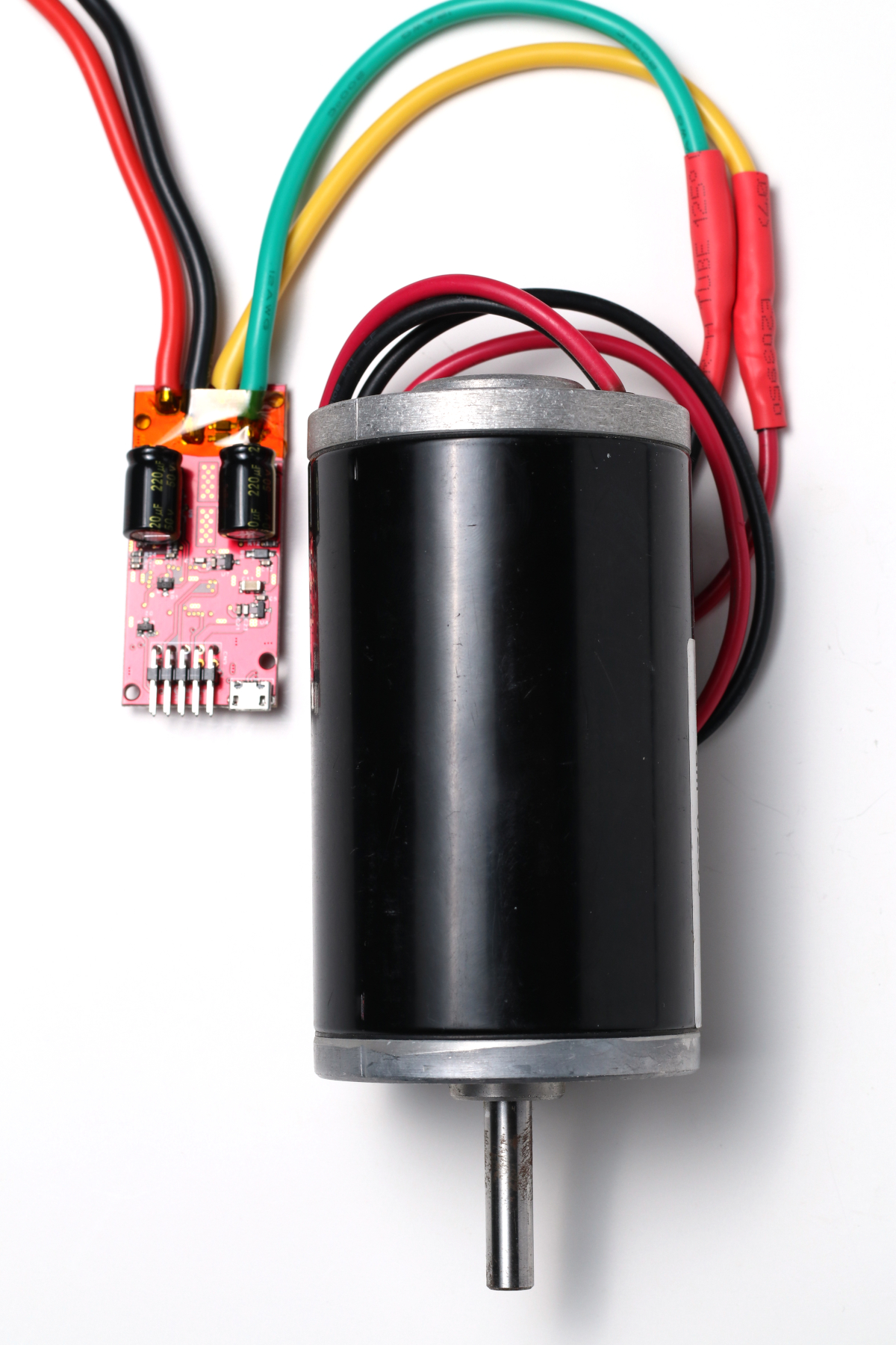
Figure 2: A motor wired to the Solo. The actual motor will vary by application. -
Wire the motor’s encoder to the controller. The signal pins of the encoder are wired to the 1A and 1B pins of the Solo’s pin header. If the encoder requires power, wire the positive connection to the 5V pin on the header and the ground connection to the header’s ground pin. See the pinout diagram below.
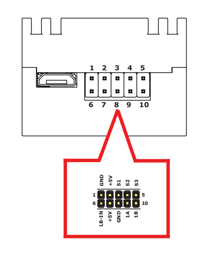
Figure 3: The Solo’s pinout. Pins 1A and 1B are used for the encoder signal lines. Figure 4: The Solo wired for a single encoder channel. -
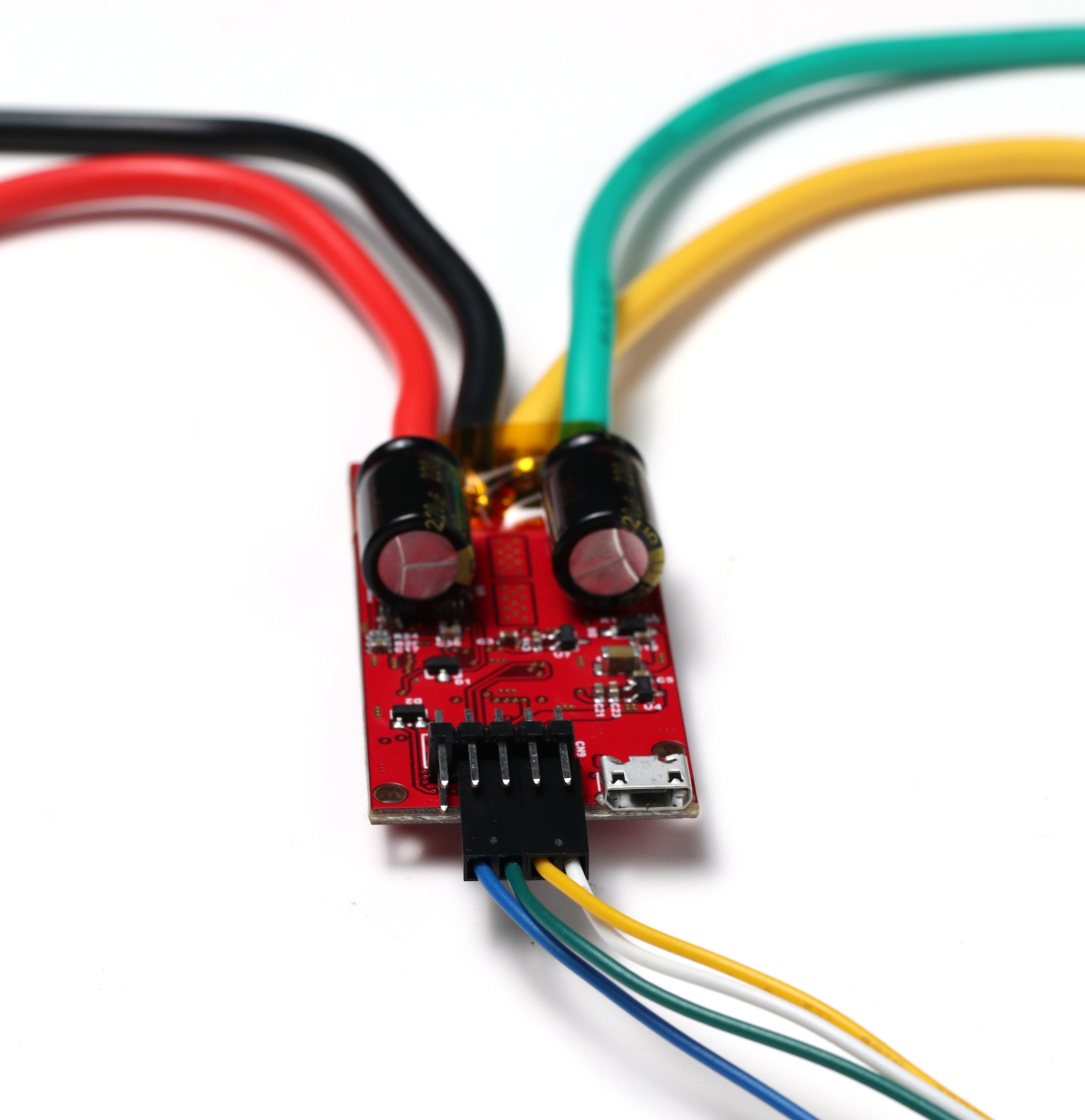
Wire the serial connection between the microcontroller and the Solo. Wire the TX line from the microcontroller to the S1 pin on the Solo and the RX line from the microcontroller to the S2 pin. Finish by connecting the ground of the microcontroller to the ground pin of the Solo. Serial communication will not work between the Solo and the microcontroller if a ground connection is not made between the two devices.
Figure 5: Pins S1 (RX) and S2 (TX) are used for serial communication. A ground connection must also be made. -
Wire the power connections of the Solo to a battery or power supply. The red wire is the positive connection and the black wire is the negative connection. The battery settings for the Solo should be set according to Configuring RoboClaw Battery Settings.
Do not wire the power source backwards or the Solo will be permanently damaged.
Most power supplies cannot absorb the regenerative voltage a motor creates when decelerating. Setting the Solo’s Max Main Battery voltage about 2 VDC above the supply’s output voltage often resolves this. If overvoltage faults persist, a voltage clamp with a dump resistor may be required.
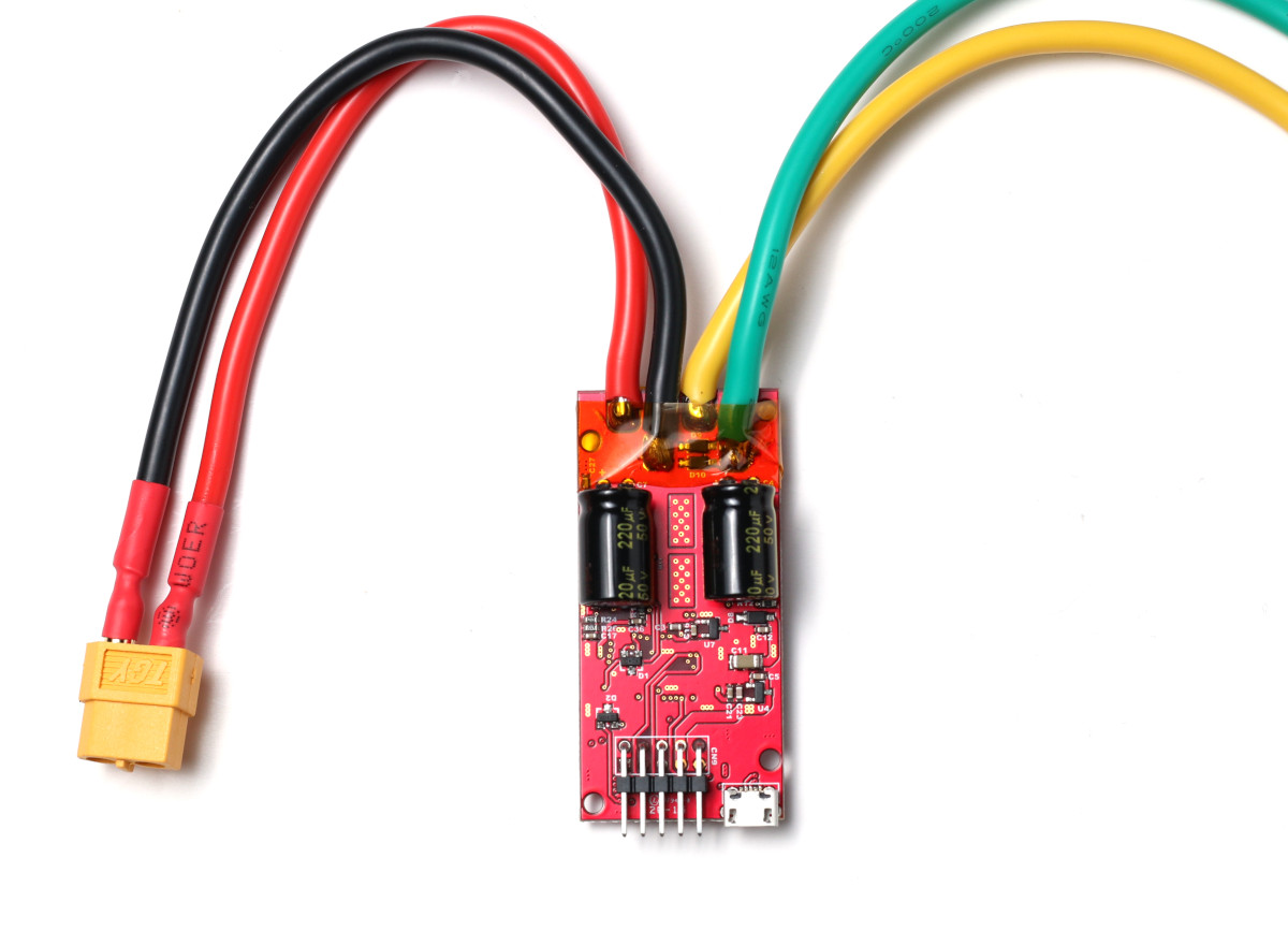
Figure 6: The power wires of the Solo with a connector added. The connector is optional.
Installing Motion Studio
-
Install Motion Studio by following Installing BasicMicro Motion Studio. Motion Studio installs from a single signed setup.exe, and no separate USB driver installation is required.
Turn on the Solo’s power source, then connect a micro USB cable between the Solo and the computer.
The Solo is not a USB powered device; the USB cable does not supply power to it. Power the Solo from its main power source before connecting the USB cable.
Testing the Motor and Encoder
-
Open Motion Studio and connect to the Solo by clicking “Connect Selected Unit” in the upper left-hand side of the application. Click on “PWM Settings” in the left-hand pane. Find the box labeled “Control” and slide the slider for Motor 1. The motor should turn forwards when sliding the slider up and backwards when sliding down. If the motor turns the wrong direction, reverse the motor wiring or reverse the motor direction in the General Settings window.
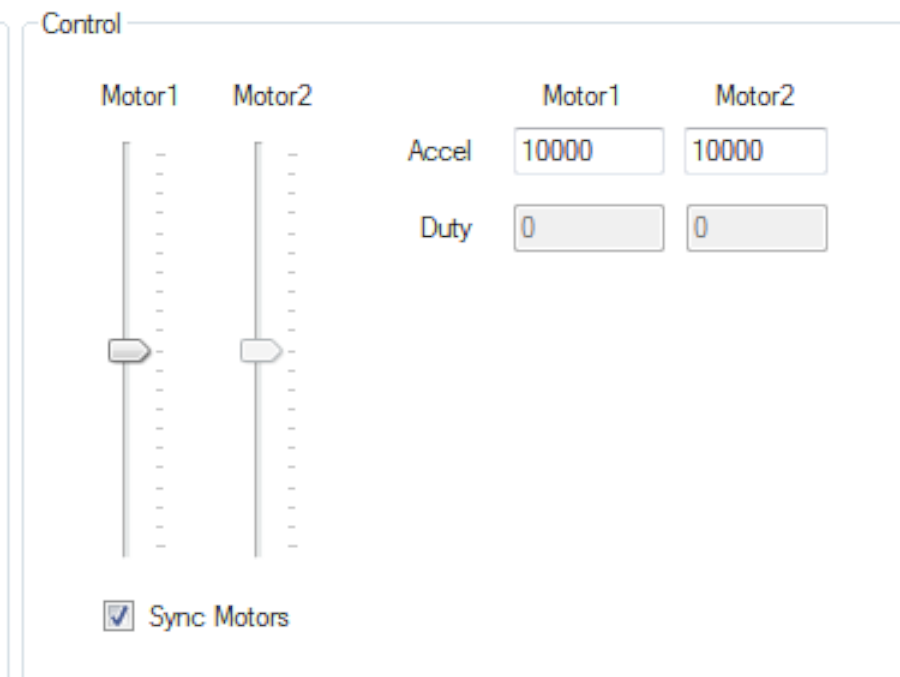
Figure 7: The motor control sliders used for testing. Only channel 1 is used with the Solo. -
Test the encoder while still in the PWM Settings window. Move the Motor 1 slider forwards and backwards. The “M1 Encoder” value at the top of the window should increment when the motor moves forwards and decrement when it moves backwards. If the counts run the wrong direction, reverse the encoder signal connections.
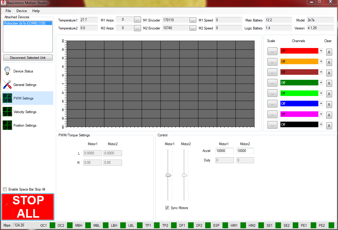
Figure 8: The encoder count is at the top of the PWM Settings window. -
The motor and encoder combination must be tuned for position control. See Auto Tuning with Motion Studio for instructions on auto-tuning. Be sure to use the PIV tuning method when auto-tuning for position control. A minimum and maximum position should be set, and the range of motion checked after the tuning process.
Setting the Control Mode
-
Click on General Settings in the left-hand pane. Find the area labeled Setup and set the Control Mode to Packet Serial. Next, find the area labeled Serial and set the field labeled Packet Serial Address to 128. Finally, in the same area, set the field titled Baudrate to the baudrate that will be used with the microcontroller. Make a note of the address and baudrate — these values will be used in the code running on the microcontroller.
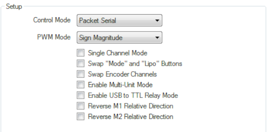
Figure 9: The location used for setting the control mode. -
Save the settings to the board by clicking “Device” in the menu at the top of the application and then clicking “Write Settings”.
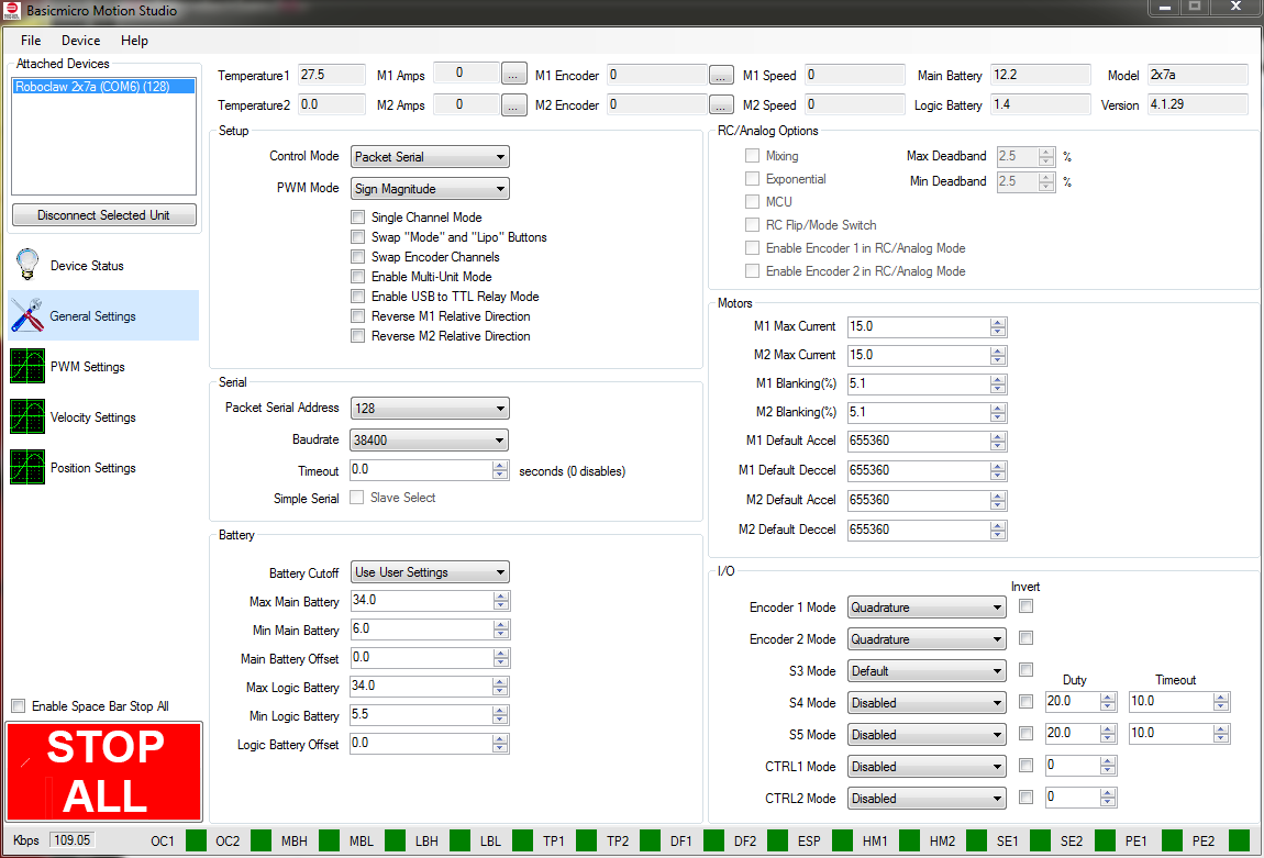
Figure 10: The device settings are saved from the Device menu.
Next Steps
Now that the Solo is configured, code can be run on the microcontroller to control it. See these application notes and example code:
- Simple Arduino Control of the RoboClaw
- Using the RoboClaw Arduino Library
- GitHub repository of example code
