RoboClaw motor controllers combine motor outputs, encoder inputs, a built-in 5V BEC, and multiple control modes (RC, analog, serial) on one board. This guide tours the board layout, key features, usage basics, and the voltage, current, and temperature limits that apply across the RoboClaw lineup.
The RoboClaw has a wide range of features and capabilities that allow you to create a variety of robotics projects. This guide is an overview of the RoboClaw board and guidelines on using it successfully.
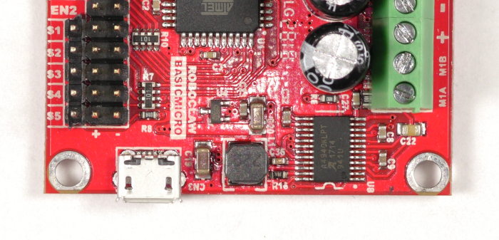
This guide applies to all RoboClaw models. The images shown are of the RoboClaw 2x7A; the layout of other models is similar.
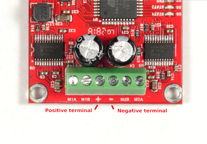
Power Terminals
The RoboClaw has two terminals for connecting your choice of a power source. The terminals are labeled (+) and (-) for positive and negative respectively. A battery is the recommended power source for all RoboClaw boards. See this app note for information on proper wire termination and the user manual for a guide to using power supplies with RoboClaw.
Do not wire the power source backwards or the RoboClaw will be permanently damaged.
Most power supplies cannot absorb the regenerative voltage a motor creates when decelerating. Setting the RoboClaw’s Max Main Battery voltage about 2 VDC above the supply’s output voltage often resolves this. If overvoltage faults persist, a voltage clamp with a dump resistor may be required.
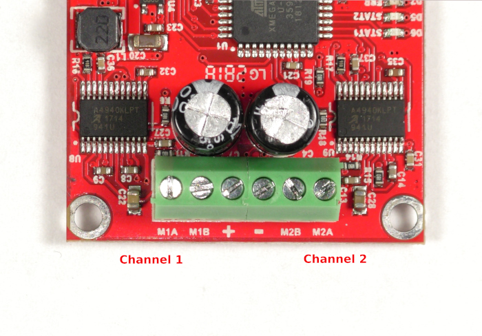
Motor Terminals
On either side of the power connections are the motor terminals. They are labeled M1A/M1B and M2A/M2B, and each pair of terminals represents a single channel for a motor. The direction each motor turns is determined by which way the motor wires are connected to these terminals. If you want each motor to operate the same, wire both motors in the same order on each set of terminals. If the motors do not turn the direction you want when testing, you can reverse the order of the wires at the terminals.
Pin Headers
The pin headers on the RoboClaw are used for a variety of functions and are labeled accordingly. The headers are 0.1″ pitch and work with any connector suited to that pitch, such as DuPont jumper wires and standard RC servo connectors. Always note the polarity marked on the board for each header.
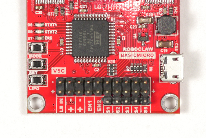
LB In
This pair of pins is for using a separate battery to power the RoboClaw’s internal logic circuitry. When driving heavy loads the RoboClaw can experience brownouts when the voltage sags below 5VDC, leading to the RoboClaw operating improperly. Note that the header is polarized, with the pin closest to the board edge as the positive pin.
Encoder Power
Next to the LB In header are a pair of headers used to power encoders. They are labeled with (+) and (-). These headers provide 5VDC for two encoder channels, one per header. Note that these headers are polarized, with the positive pin being the one closest to the board edge.
ENC1 and ENC2
The two headers labeled ENC1 and ENC2 are the encoder input headers. Each header is used for a single encoder, with inputs for both the A and B channels of a quadrature encoder. If you are using quadrature encoders, be sure that the leading channel is attached to the pin closest to the board’s edge; if the encoder channels are wired backwards they will not indicate direction and counts properly. When using potentiometers, analog encoders, or absolute encoders, connect the output of the encoder to the pin closest to the board edge. After wiring your encoders you can check their operation in Motion Studio, ensuring that the pulses are counted properly and that the motion of the motor corresponds to the encoder counting.
S1 and S2
Headers S1 and S2 are used for a variety of purposes. In RC and analog modes these headers act as inputs from radio receivers, potentiometers, and joysticks. In packet and standard serial modes these pins act as RX and TX channels for serial communications as well as slave select inputs. There are three pins on each of these headers. The pin closest to the board’s edge is the signal pin, the middle pin is positive, and the pin on the inside edge of the board is the negative pin.
S3 Through S5
These pin headers can be used for a handful of functions different from those of S1 and S2. S3 can be used as a flip switch to change motor directions in RC mode. These headers are also used for voltage clamping functionality, limit switches, home switches, and e-stops.
The BEC
The RoboClaw has an onboard BEC, a voltage regulator that supplies a 5VDC source of power used by the RoboClaw itself and also available to power external components such as microcontrollers, RC receivers, and encoders. The 5VDC source is available at any of the positive pins on the pin headers except for the LB In header. Similarly, the ground pin on any of the headers, besides LB In, can be used as a common ground for devices connected to the RoboClaw. See this app note for more details about the RoboClaw’s BEC.
Status LEDs
There are three small LEDs labeled STAT1, STAT2, and ERR. These are used to indicate the status of the RoboClaw. In normal operation the STAT1 LED blinks rapidly when connected to Motion Studio, and the STAT1 and STAT2 LEDs will light up and stay lit when a motor channel is active. When the RoboClaw encounters problems these LEDs are also used to indicate a variety of warnings and fault conditions. See this app note or the manual for further information.
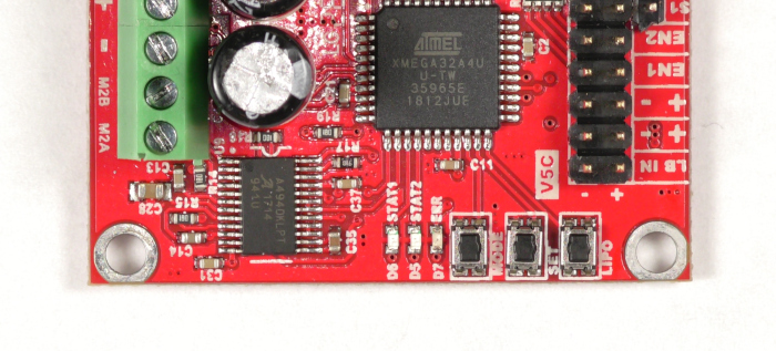
Buttons
Current RoboClaw hardware no longer has buttons and must be configured from Motion Studio. The button section applies to hardware revisions V5 and under. For configuring a RoboClaw with Motion Studio, see the Solo Quick Start Guide and the Dual Channel RoboClaw Quick Start Guide.
On hardware revisions V5 and under there are three buttons labeled MODE, SET, and LIPO. These buttons can be used to set the mode of the RoboClaw as well as other related settings. See this app note or the manual for information about using these buttons.
Micro USB Port
On the edge of the board there is a micro USB connector. It is used when connecting the RoboClaw to a computer for configuration with Motion Studio. When the RoboClaw is connected via USB it can receive commands and operate both motor channels. Please note that the RoboClaw cannot be powered via the USB port and always requires that a power source be connected to the power terminals.
Control Modes
The RoboClaw has several different control modes that are suitable for a wide range of projects. In RC mode the RoboClaw can be controlled via an RC radio system or a microcontroller emulating one. Analog mode allows for the use of potentiometers or joysticks as a control input. Packet serial mode allows two-way communication with a microcontroller for both control and feedback. Finally, simple serial mode allows a microcontroller to send simple byte commands to the board for control of both motor channels.
Safety
The RoboClaw has several features to protect itself. Current limiting is automatic and the setpoint for current limiting can be set by the user in Motion Studio. The RoboClaw also has automatic temperature protection with preset setpoints. In the case of both types of protection the board will take the appropriate action to prevent damage to itself.
Encoders
RoboClaw can be used with both absolute and quadrature encoders and supports a decoding rate of up to 19.9 million pulses per second. Encoders allow the RoboClaw to precisely control both the speed and position of both motor channels.
PID Control
RoboClaw can use what is known as PID control when it controls the speed and direction of motors attached to it. It allows the RoboClaw to maintain speed and position properly even when there are load changes to a motor. The P, I, and D parameters can be automatically set by the tuning system in Motion Studio or be manually set by the user.
What Are the RoboClaw’s Limits?
Each RoboClaw has voltage limitations, including minimum and maximum voltages. This is the case for both the main battery as well as the logic battery. User-defined minimum and maximum voltages can also be set for the RoboClaw via Motion Studio.
| RoboClaw Model | Minimum Battery Voltage | Maximum Battery Voltage |
|---|---|---|
| Solo 30A, Solo 60A | 6V | 34V |
| 2x7A | 6V | 34V |
| 2x15A, 2x30A, 2x45A, 2x60A | 6V | 34V |
| 2x60AHV 60VDC | 6V | 60V |
| 2x200A 60VDC, 2x300A 60VDC | 10V | 60V |
| Solo 300A | 10V | 60V |
There are also current limitations for each model. A RoboClaw’s name indicates its continuous current rating per channel — a 2x30A supplies up to 30 amps continuously on each of its two channels — and each model can supply a higher peak current for short periods. User-defined current limits can also be set via Motion Studio.
Exact continuous and peak current ratings vary by model and hardware revision. Check the datasheet on your model’s product page for its ratings.
Every RoboClaw has predefined temperature limits to prevent damage to the board. At 85°C the RoboClaw will throw a warning and at 100°C it will throw a fault. If a RoboClaw has a fan installed, it will turn on at 45°C and turn off at 35°C.
What Precautions Apply?
There are several precautions to observe when wiring and operating a RoboClaw.
Never disconnect a motor from the RoboClaw while the board is powered, and always make sure the motors are stopped before powering down. A spinning motor generates voltage that can back-feed and erratically operate an unpowered RoboClaw. If you plan to run the RoboClaw in bridged mode, configure it in Motion Studio before wiring the motor or the board may be damaged.
When removing power from a RoboClaw, always disconnect the positive lead before the negative lead.
Next Steps
These guides continue from here with wiring, configuration, and power details: