Introduction
This Application Note is the first in a series of articles covering the usage and functionality of BasicMicro Motion Studio. This App Notes covers the layout, general features and commonly used operations of Motion Studio. Having a copy of Motion Studio open while reading this is recommended.
See this App Note for instructions on installing Motion Studio.
Motion Studio Layout
Top Status Bar
In the upper section of Motion Studio is a status bar indicating aspects of the currently connected RoboClaw. This status bar is always visible regardless of the sub-section of the application being used.The status bar has information on board temperature, motor channel current, encoder counts, motor speed, main battery voltage, logic battery voltage as well as firmware and hardware version information.
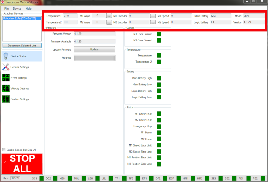
Figure 1: Location of the top status bar.
Bottom Status Bar
The status bar at the bottom of the application displays warnings and error conditions for the connected RoboClaw. A full listing of the states can be seen by accessing the “Device Status” section of the application. Simply click on “Device Status” on the left-hand side of the application to go there.
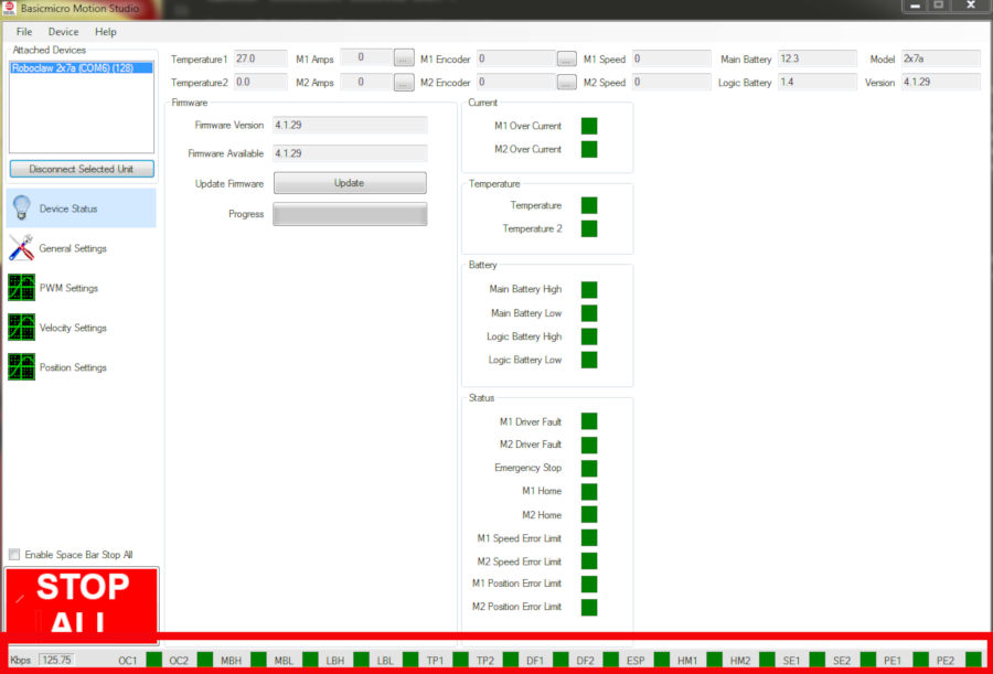
Figure 2: Location of the bottom status bar.
Device Status
The Device Status section of Motion Studio can be accessed by clicking on “Device Status” on the left-hand side of the application. This sections is the one that is seen what Motion Studio starts. It contains sub-sections to update firmware and a listing and indications of the warning and error states of the connected RoboClaw.
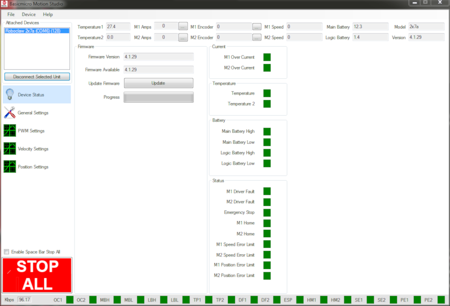
Figure 3: The device status screen.
General Settings
The General Settings section of Motion Studio is where the majority of the settings in Motion Studio are found. The sub-section labeled “Setup” is where the control mode is set as well as options related to it. The “Serial” section is used to configure the hardware address and baudrate for serial communications. The “Battery” section is used to configure cutoff settings for both the main battery and logic battery. The section labeled “RC/Analog Options” is for setting options related to the RC and Analog control modes. Here mixing can be enabled for differential drive and exponential set to allow for easier control of a robot. The “Motors” section is used to set current limits as well as acceleration and deceleration values for each motor channel. Finally the section labeled “I/O” configures the various modes of operation for pins S3 through S5 such as e-stop, limit switches and home switches.
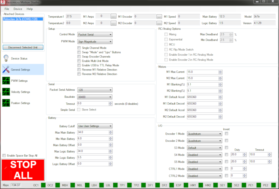
Figure 4: The general settings screen.
PWM Settings
Clicking “PWM Settings” on the left-hand side of the application opens up the PWM Settings section. Here both motor channels can be operated manually to test the operation of the motors and encoders. This section also contains graphing functionality so that various aspects of the motors and controller can be graphed together over time. This functionality is useful for testing motors, tuning encoders and verifying the proper operation of components attached to the motors.
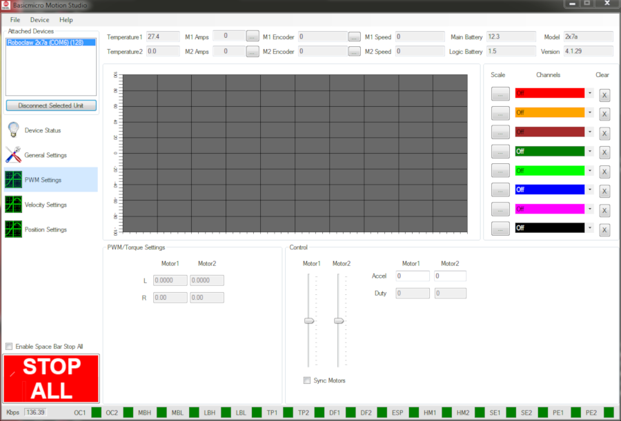
Figure 5: The pwm settings screen.
Velocity Settings
The Velocity Settings section of Motion Studio is accessed by click on “Velocity Settings” on the left-hand side of the application. This section is used to manually and automatically tune motor and encoder combinations. As with the “PWM Settings” section both motor channels can be operated manually and motor/encoder parameters graphed against each other over time.

Figure 6: The velocity setting screen.
Position Settings
Clicking “Position Settings” on the left-hand side of the application opens up the section where motor and encoders can be tuned for position control with the RoboClaw. Before using this section the motor and encoder combination must be tuned for velocity in the “Velocity Settings” section. This section too contains graphing functionality to use alongside the tuning routines.
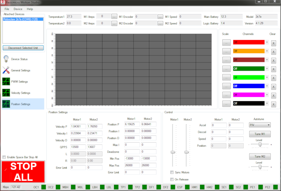
Figure 7: The position settings screen.
Common Operations in Motion Studio
Connecting and Disconnecting a RoboClaw
After starting Motion Studio a RoboClaw must be connected to the application. In the upper left-hand corner of the application is a window that shows all of the RoboClaws visible to Motion Studio. To connect a RoboClaw select one from the list then click “Connect Selected Unit”. The “Stat1” LED on the RoboClaw will flash rapidly when it’s connected to Motion Studio. To disconnect the RoboClaw click on the same button used to connect the RoboClaw, it should be labeled “Disconnect Selected Unit”.
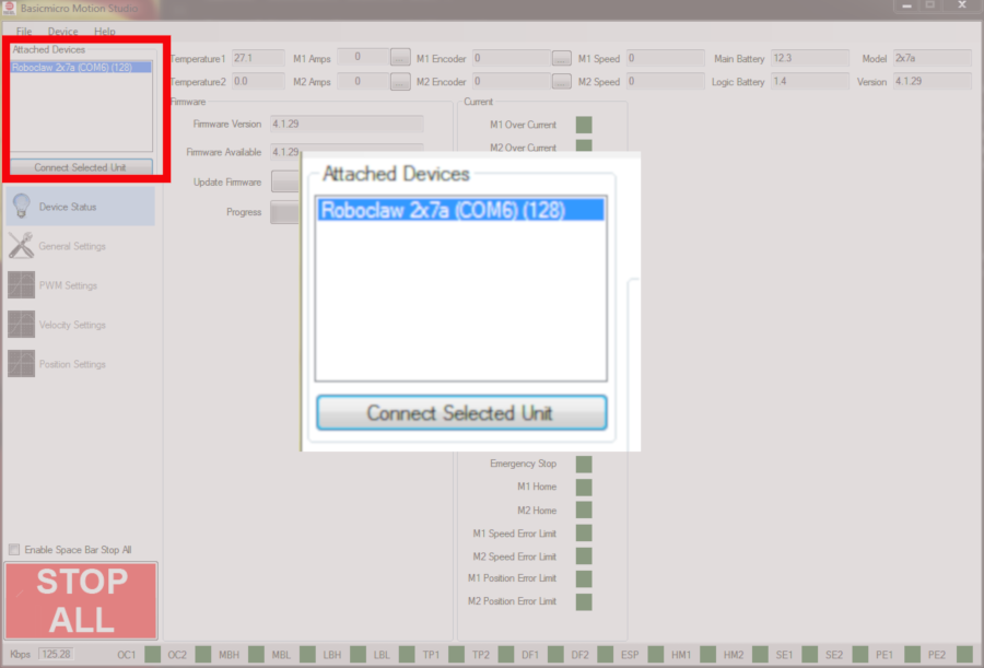
Figure 8: Location to connect and disconnect a RoboClaw.
Updating Firmware
The firmware for the RoboClaw motor controller can be updated from inside Motion Studio. Click on “Device Status” on the left side of Motion Studio. Now locate the section labeled “Firmware”. There are two fields at the top of this section indicating the firmware currently on the board and the firmware version available from BasicMicro. If the two versions are the same the firmware does not need to be updated. If there is a difference in versions the firmware must be updated. To update the firmware click on the button labeled “Update”. A dialog box will pop up with information on the new firmware, click “OK” and the update process with start. The RoboClaw will disappear from the list of devices and then be re-added to the list once the process completes. After updating the firmware the RoboClaw must be reconnected by clicking “Connect Selected Unit” to continue using Motion Studio.
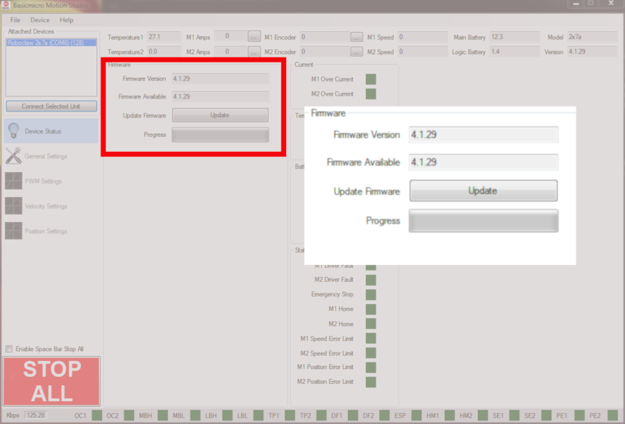
Figure 9: Location to update firmware.
Saving Settings to Board
After making any changes to the settings in Motion Studio the changes must be saved to the motor controller. This is done by clicking “Device” in the menu at the top of the application and then clicking on “Write Settings”. Once this is done the settings have been saved to the board and the board can be disconnected from Motion Studio.

Figure 10: Menu option to save settings to the board.
Restoring Default Values
An attached RoboClaw can be set back to its factory settings easily. Click on “Device” in the menu at the top of the application and then click on “Restore Defaults”.
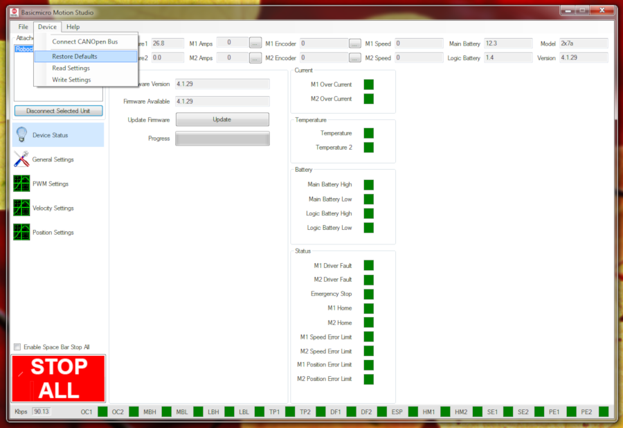
Figure 11: Menu option to restore default values.
Save and Load Configuration Settings
The setting for the RoboClaw can be saved to a file or restored from a previously created file. To save the settings to a file click on “File” in the menu at the top of the application and then click on “Save Settings”. A dialog will open where the file location and name can be set. Click on “Save” to write the settings to the file. To load settings from a file click on “File” in the menu at the top of the application and then click on “Load Settings”. Select the file from the dialog that opens and click on “Open” to load the file.
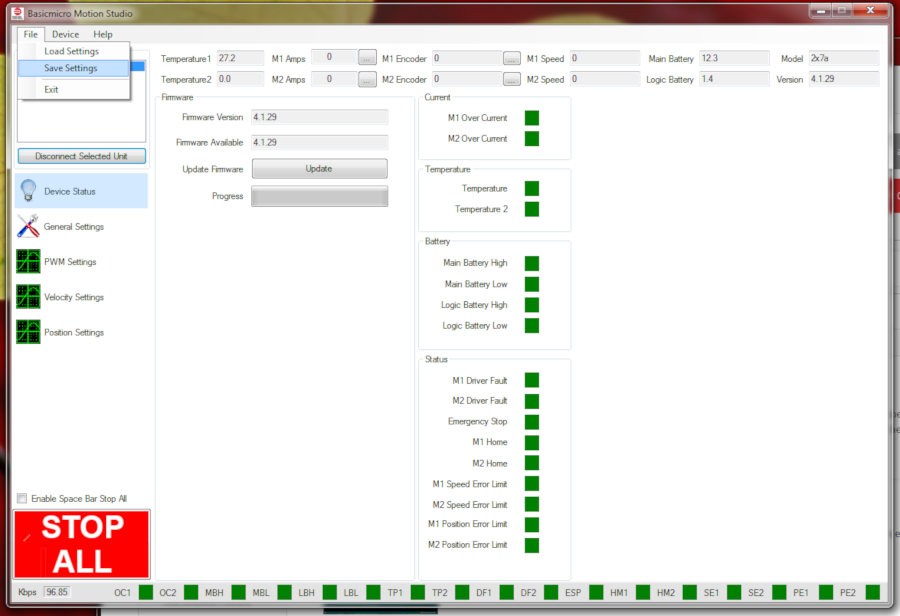
Figure 12: Menu option to save and load configuration file.
Stop All Button
The “Stop All” button in the lower left-hand corner of the application is used to stop both motors quickly and easily. Clicking the button stops both motors. There is also a checkbox that if checked allows the use of the space bar as an alternative to clicking the button.
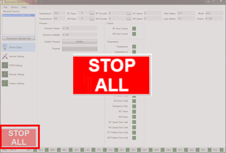
Figure 13: Location of the stop all button.
For further information about Motion Studio consult the manual.