The General Settings screen in BasicMicro Motion Studio is where most RoboClaw configuration happens. The screen is divided into seven panes: General, Serial, Battery, Encoders, RC/Analog Options, Motors, and I/O. This guide walks through each pane and explains the purpose and function of every setting.
Sections of the General Settings Screen
The majority of the settings for the RoboClaw are configured on the General Settings screen of Motion Studio. The screen is divided into panes that group related settings together. Some options may appear grayed out, indicating they are not available for the currently selected control mode.
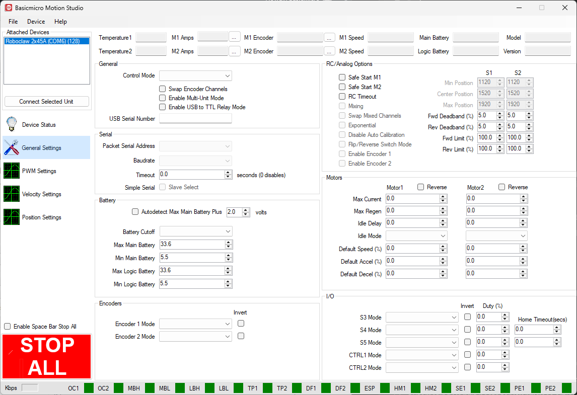
After making changes, the settings must be written to the motor controller to take effect: click “Device” in the menu at the top of the application, then click “Write Settings”. Motion Studio resets the controller automatically after writing. Settings can also be saved to a file and restored later from the “File” menu.
General
Figure 2: Location of the General pane (1) in the General Settings screen.
The General pane (1) holds the control mode selection and the main configuration options.
Control Mode: Selects the active control mode of the RoboClaw. The available modes are Packet Serial, Simple Serial, Analog, and RC.
Packet Serial: A bidirectional serial mode used when controlling the RoboClaw from a USB connection or the serial port of a microcontroller. A wide range of commands can be sent and data read back from the controller. The full command set is documented in the RoboClaw user manual on the BasicMicro downloads page, and libraries are available for Arduino and Python. See Using the RoboClaw Arduino Library for an introduction to the Arduino library.
Simple Serial: A one-way serial mode where single bytes are sent instead of packet commands. It allows a simpler control scheme but is not as feature rich as packet serial mode, and encoder feedback is not supported.
Analog: Controls motor speed and direction with 0 V to 2 V analog inputs from potentiometers, an analog joystick, or filtered PWM from a microcontroller.
RC: Allows a hobby RC radio system, or servo-style pulses from a microcontroller, to control the motor controller.
Swap Encoder Channels: Swaps the encoder channels between the two motor channels.
Enable Multi-Unit Mode: Sets the S2 pin to open drain, allowing multiple RoboClaws to be controlled from a single serial port in packet serial mode. The setting must be enabled on each RoboClaw in use, and each unit must have a unique packet serial address.
Enable USB to TTL Relay Mode: Allows USB serial commands to be passed through the master RoboClaw via the S1 (RX) and S2 (TX) pins, so multiple networked RoboClaws can be controlled from a single USB-connected master unit. Each RoboClaw must have a unique packet serial address.
USB Serial Number: Assigns a serial number of up to 18 characters that is saved to the motor controller, making individual units easy to identify when several are connected.
Serial
Figure 3: Location of the Serial pane (1) in the General Settings screen.
The Serial pane (1) holds the settings for the serial control modes.
Packet Serial Address: Sets the address used in packet serial mode and USB to TTL relay mode. Eight addresses are available, from 128 to 135, with 128 as the default. When multiple RoboClaws share a serial bus, each must have a unique address.
Baudrate: Sets the serial communication speed. Rates from 2400 to 460800 bps are supported, and the baudrate set on the RoboClaw and on the microcontroller or computer must match for communication to work properly. USB connections ignore this setting: the USB virtual COM port always communicates at the maximum speed supported by both devices.
Timeout: Sets the communication timeout, from 0 to 25.5 seconds. If no command is received within the set period, the motors are stopped. The default value of 0 disables the timeout.
Simple Serial (Slave Select): Enables the slave select option for using multiple RoboClaws in simple serial mode. Setting pin S2 high enables the attached RoboClaw; pulling S2 low causes all commands to be ignored. This allows a specific RoboClaw in a group to be selected to receive and execute commands.
Battery
Figure 4: Location of the Battery pane (1) in the General Settings screen.
The Battery pane (1) sets the voltage limits for the main and logic batteries.
Autodetect Max Main Battery Plus: When enabled, the RoboClaw detects the maximum main battery voltage automatically and adds the offset entered in the volts field. Auto-detection requires a properly charged battery.
Battery Cutoff: Selects a battery cutoff preset based on Lithium Polymer cell count. A preset overrides the user-defined voltage limits unless “Use User Settings” is selected. The “Auto Detect” option determines the cell count from the voltage measured at power-up, so an over-charged or under-charged battery can prevent proper detection.
Max Main Battery: Sets the maximum main battery voltage. The motor controller decelerates the motors as needed to prevent regenerative voltage from exceeding this limit.
Min Main Battery: Sets the minimum main battery voltage. The motor controller enters freewheel mode if the voltage drops below this limit to protect the battery.
Max Logic Battery: Sets the maximum logic battery voltage. Exceeding it triggers a motor control error to protect the internal circuitry.
Min Logic Battery: Sets the minimum logic battery voltage. Dropping below it triggers a motor control error to protect the internal circuitry.
For a walkthrough of choosing these values, see Configuring RoboClaw Battery Settings.
Encoders
Figure 5: Location of the Encoders pane (1) in the General Settings screen.
The Encoders pane (1) sets the type of encoder attached to each channel.
Encoder 1 Mode: Selects the encoder type and direction for motor channel 1. The options are quadrature and absolute, and the Invert checkbox reverses the signal direction. If there is any confusion about the type of encoder being used, reference the documentation for the encoder.
Encoder 2 Mode: Selects the encoder type and direction for motor channel 2, with the same options as channel 1.
RC/Analog Options
Figure 6: Location of the RC/Analog Options pane (1) in the General Settings screen.
The RC/Analog Options pane (1) configures how the RoboClaw responds to RC and Analog control inputs.
Safe Start M1 and Safe Start M2: Enable Safe Start for the motor channel. The control input must return to center before the motor will start.
RC Timeout: Stops the motors if the input signal is lost for more than 100 ms. Not available in Analog mode.
Analog Error Detect: Stops the motors if an analog input reads 0 or 2047, which indicates a failed potentiometer.
Mixing: Enables mixing of the S1 and S2 inputs for differential drive control. S1 sets forward and reverse speed and S2 controls turning, similar to RC car steering. Disable it to control each motor independently, tank style.
Swap Mixed Channels: Swaps the roles of M1 and M2 in mixing.
Exponential: Lessens the control response around the center of the input range, adding low-speed sensitivity and making a robot or vehicle easier to control.
Disable Auto Calibration: Disables automatic pulse calibration, allowing a slow microcontroller to send RC-style pulses at lower than normal RC rates.
Flip/Reverse Switch Mode: Enables the flip/reverse function on S3. When activated, both motor directions are reversed, which is useful when a robot is flipped over. The input is active-low by default unless the pin is inverted, and S3 must be set to Flip/Reverse Switch in its drop-down menu in the I/O pane.
Enable Encoder 1 and Enable Encoder 2: Enable the encoder channel for use in RC or Analog mode. The encoder controls motor speed or position depending on the selected PID mode. Speed is scaled using the QPPS value, and position is limited by the set minimum and maximum position values.
Min Position, Center Position, and Max Position: Set the minimum, center, and maximum input values when auto calibration is disabled. In RC mode the values are in microseconds; in Analog mode the 0 V to 2 V input range maps to 0 to 2047.
Fwd Deadband (%) and Rev Deadband (%): Set the forward and reverse input range near neutral that is ignored and treated as zero throttle.
Fwd Limit (%) and Rev Limit (%): Cap the maximum forward and reverse output by limiting the PWM duty cycle to less than 100%.
Motors
Figure 7: Location of the Motors pane (1) in the General Settings screen.
The Motors pane (1) sets the drive method, current limits, and default motion values for each motor channel.
Motor1 Reverse and Motor2 Reverse: Reverse the direction of the motor channel.
PWM Mode: Selects the PWM drive method used to power the motors. Most applications should leave this at the default setting.
Max Current: Sets the maximum current for each motor channel, up to the RoboClaw’s rated peak. When the limit is reached, motor power is automatically limited and a warning condition is shown on the board’s LED indicators and in Motion Studio. The actual limit decreases with temperature, from the peak rating at 25 °C down to the continuous rating at 85 °C, then ramping to zero by 100 °C.
Max Regen: Sets the maximum regenerative current allowed during braking or deceleration. Use a negative value to limit the current flowing back into the battery.
Idle Delay: Sets the delay before switching to freewheel mode when the motor duty cycle reaches zero. It applies only when Idle Mode is set to freewheeling; the braking state is held for the specified time before releasing. Braking mode does not time out.
Idle Mode: Selects the idle behavior for each channel. Free Wheeling removes all power from the motors, while Electric Braking shorts the motor windings to resist motion.
Default Speed (%): Sets the maximum speed of a position movement for RC, Analog, or packet serial position commands that have no speed argument. An encoder is required.
Default Accel (%) and Default Decel (%): Set the default acceleration and deceleration for RC, Analog, or packet serial commands. Commands that include their own accel or decel arguments override these defaults.
I/O
Figure 8: Location of the I/O pane (1) in the General Settings screen.
The I/O pane (1) configures the alternate functions of the S3, S4, and S5 pins, and the CTRL1 and CTRL2 output pins on models that have them. These pins can be set up for functions such as home switches, limit switches, voltage clamping, emergency stops, and monitoring outputs.
S3 Mode, S4 Mode, and S5 Mode: Assign an alternate function to the pin from its drop-down menu. The available modes are listed in the table below. Some functions are channel specific: S4 is assigned to Motor 1 and S5 is assigned to Motor 2, so the corresponding motor must be connected to the appropriate sensor or input.
Invert: Sets the pin’s input signal to active-high. The default is active-low.
Duty (%): Sets the PWM duty for the alternate functions that use one.
Home Timeout (secs): Sets the timeout for the homing functions.
CTRL1 Mode and CTRL2 Mode: The CTRL1 and CTRL2 pins, available on select RoboClaw models, can be configured with many of the same functions as S3 through S5. Unlike the S pins, they are MOSFET-driven outputs and can directly drive loads such as brakes; refer to the model’s datasheet for the maximum supported current.
| Pins | Mode | Description |
|---|---|---|
| S3, S4, S5 | Disable | Disables the pin. This is the default for S4 and S5. |
| S3, S4, S5 | Default | Acts as a flip switch in RC and Analog modes, or as a latching e-stop in serial modes. |
| S3, S4, S5 | E-Stop (Latching) | Stops all motion until the RoboClaw is reset and the e-stop signal clears. |
| S3, S4, S5 | E-Stop | Stops all motion until the e-stop signal clears. |
| S3, S4, S5 | Stop M1 | Stops Motor 1 as a non-fault condition while the input signal is active. The motor resumes when the signal is released. |
| S3, S4, S5 | Stop M2 | Stops Motor 2 as a non-fault condition while the input signal is active. The motor resumes when the signal is released. |
| S3, S4, S5 | Stop M1/M2 | Stops both motors as a non-fault condition while the input signal is active. The motors resume when the signal is released. |
| S3, S4, S5, CTRL1, CTRL2 | Main Battery Warning | Sets the pin low (or high if Invert is checked) when the Max Main Battery voltage is exceeded. Can drive an LED or a TTL-compatible signal line. |
| S3, S4, S5, CTRL1, CTRL2 | Logic Battery Warning | Sets the pin low (or high if Invert is checked) when the Max Logic Battery voltage is exceeded. Can drive an LED or a TTL-compatible signal line. |
| S3, S4, S5, CTRL1, CTRL2 | User Output | User-settable PWM output from 0 to 100% duty, set via packet serial commands. Can act as a basic analog output if filtered. |
| S3, S4, S5, CTRL1, CTRL2 | Main Battery Output | Outputs a PWM signal representing the main battery voltage, with 0 to 100 V scaled to 0 to 100% duty. The signal must be filtered and calibrated against a known voltage to be usable. |
| S3, S4, S5, CTRL1, CTRL2 | Logic Battery Output | Outputs a PWM signal representing the logic battery voltage, with 0 to 100 V scaled to 0 to 100% duty. The signal must be filtered and calibrated against a known voltage to be usable. |
| S3, S4, S5, CTRL1, CTRL2 | Current M1 Output | Outputs a PWM signal representing Motor 1 current, scaled from 0 to 100% duty. The signal must be filtered and calibrated against a packet serial current reading. |
| S3, S4, S5, CTRL1, CTRL2 | Current M2 Output | Outputs a PWM signal representing Motor 2 current, scaled from 0 to 100% duty. The signal must be filtered and calibrated against a packet serial current reading. |
| S3, S4, S5, CTRL1, CTRL2 | Temperature 1 Output | Outputs a PWM signal representing temperature 1, with 0 °C to 100 °C scaled to 0 to 100% duty. The signal must be filtered and calibrated to be usable. |
| S3, S4, S5, CTRL1, CTRL2 | Temperature 2 Output | Outputs a PWM signal representing temperature 2, on models with a second temperature sensor. The signal must be filtered and calibrated to be usable. |
| S3, S4, S5, CTRL1, CTRL2 | Voltage Clamp | Activates an external voltage clamp circuit to dissipate excess regenerative energy, recommended when running from a power supply. Triggers 1 V above the set voltage limit and releases when the voltage drops back to the limit. |
| S3, S4, S5, CTRL1, CTRL2 | Brake | Provides a control signal for an external brake circuit. On some models, CTRL1 and CTRL2 can drive a brake directly. |
| S3 | RS485 Direction | Outputs a read/write direction signal for RS-485 adapters. |
| S3 | Encoders Enable/Disable | Toggles encoder support in RC and Analog modes. Encoder feedback is disabled while the signal is active and enabled while it is inactive. |
| S3 | Flip/Reverse Switch | Flip/reverse input. When activated, motor direction toggles, which is ideal for reversing the controls if a robot flips over. Active-low by default; use Invert to change the active state. |
| S4, S5 | Motor Brake Ctrl | Activates when the pin’s motor stops and releases when the motor starts. |
| S4, S5 | Motor Home (Auto) | On startup, the motor moves until the switch is triggered or the timeout elapses. If the switch is already triggered at startup, the motor moves forward for 3 seconds to clear it, then returns. During normal operation, triggering the switch stops the motor and zeroes the encoder. |
| S4, S5 | Motor Home (User) | Sets the reverse limit switch to act as a home switch. The motor is driven by user commands until the switch triggers, at which point the motor stops and the encoder count resets to zero. |
| S4, S5 | Motor Home (Auto)/Limit (Fwd) | Used when two limit switches share one input. Power-up behavior matches Motor Home (Auto). Once the home switch triggers, the motor can only move forward until the switch releases. While moving forward, activation of the other switch stops the motor, after which it can only move in reverse until the switch releases. |
| S4, S5 | Motor Home (User)/Limit (Fwd) | Used when two limit switches share one input. If the switch triggers while moving in reverse, the motor stops and the encoder is zeroed. The motor can then only move forward until the switch releases. While moving forward, activation of the other switch stops the motor, after which it can only move in reverse until the switch releases. |
| S4, S5 | Motor Limit (Fwd) | Stops the motor when triggered while moving forward. |
| S4, S5 | Motor Limit (Rev) | Stops the motor when triggered while moving in reverse. |
| S4, S5 | Motor Limit (Both) | Acts as a limit input in both directions. Two switches can be wired in parallel, and the commanded direction when the switch activates determines whether it acts as a forward or reverse limit. |
External hardware is required for the voltage clamp function. For recommended hardware and wiring, see Using a Voltage Clamp with RoboClaw.
Next Steps
Once the general settings are configured, the PWM Settings screen is the place to test the motors, and the Velocity and Position Settings screens handle encoder tuning. For an overview of the rest of the application, see Introduction to Motion Studio. Detailed guides are available for each screen: PWM Settings in Motion Studio, Velocity Settings in Motion Studio, and Position Settings in Motion Studio.