Introduction
This Application Note describes how to wire, configure and operate multiple RoboClaws together using RoboClaw’s standard serial mode. In standard serial mode 1 byte commands are sent to a RoboClaw that is selected with a dedicated line for each RoboClaw in use.
Materials
(4) RoboClaw motor controllers
(4) batteries, one for each RoboClaw
(2) male jumper wires
(8) female jumper wires
(4) female to male jumper wires
(4) motors, one for each RoboClaw
(1) Arduino compatible board
(1) USB cable for the Arduino
(1) micro USB cable for the RoboClaw
(1) soldering iron
(1) solder
(1) computer with BasicMicro Motion Studio installed
(1) small screwdriver
Let’s get started
1. Wire one motor and battery to each RoboClaw. Please follow this tutorial to step 10.
2. Disconnect power from each of the RoboClaws.
3. Cut and strip one end of a male jumper wire leaving a male connector on the other end. Do the same for 4 female jumper wires. Tin the end of each stripped wire with a small amount of solder. Solder the 4 female jumpers to the male jumper to make a wiring harness. See the photo below as an example. Repeat this once more to make the harness for wiring grounds together.
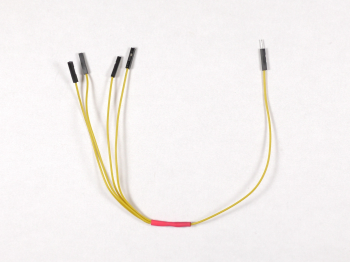
Figure 1: Signal wiring harness completed.
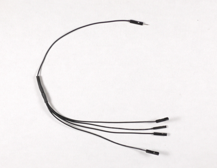
Figure 2: Ground wiring harness completed.
4. Wire the Arduino and RoboClaws together using the table below.
| Function | Arduino | RoboClaw |
| Transmit | Pin 11 | S1 signal pin on each RoboClaw (closest pin to edge of board) |
| Ground | Any Arduino ground pin | S1 ground pin on each RoboClaw (pin closest to inside of board) |
| Slave select 1 | Pin 2 | S2 signal pin on first RoboClaw |
| Slave select 2 | Pin 3 | S2 signal pin on second RoboClaw |
| Slave select 3 | Pin 4 | S2 signal pin on third RoboClaw |
| Slave select 4 | Pin 5 | S2 signal pin on fourth RoboClaw |
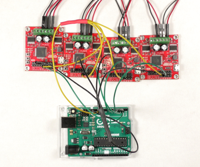
Figure 3: RoboClaws and Arduino wired together.
5. Reconnect power to each RoboClaw.
6. Connect one RoboClaw to your computer with a micro USB cable.
7. Open BasicMicro Motion Studio and connect the RoboClaw as done in the tutorial linked in step 1. Click on “General Settings” on the left-hand side of the application. Now find the pane labeled “Setup”. In the “Control Mode” dropdown select “Simple Serial”.
8. Located the pane labeled “Serial”. Set the baudrate to 38440. Finally check the checkbox for “Slave Select”.
9. Repeat steps 7 and 8 for each of the other RoboClaws to be used.
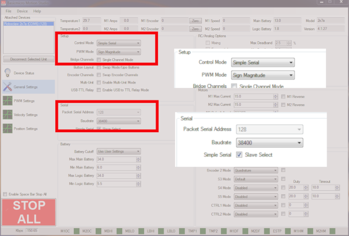
Figure 4: Settings for standard serial bus operation in Motion Studio.
10. Connnect the Arduino to your computer with a USB cable.
11. Download the sketch for this App Note from here. Open the sketch and upload it to your Arduino.
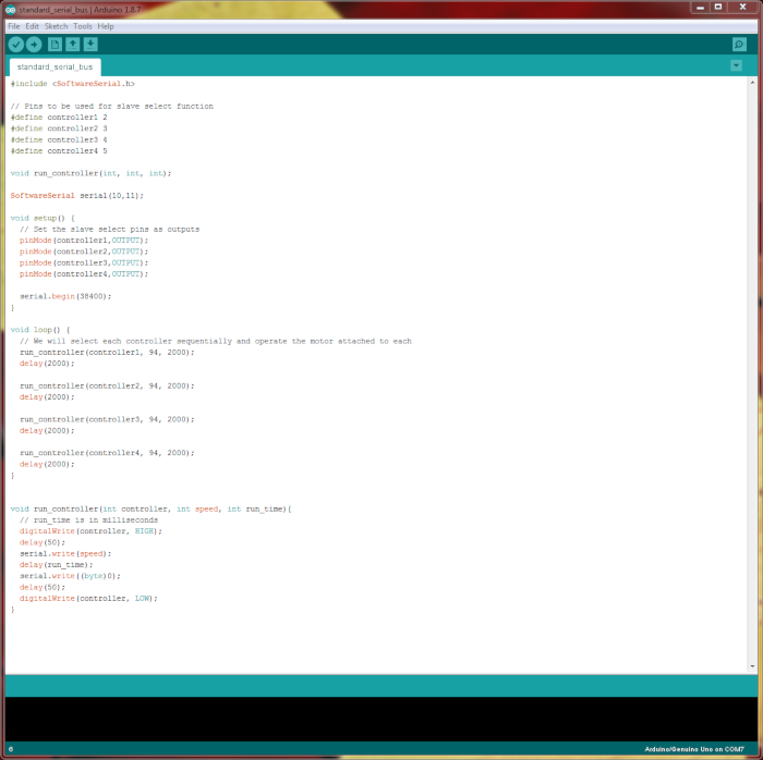
Figure 5: The Arduino sketch used in the App Note.
12. Test the operation of the RoboClaws with the Arduino sketch. One by one the motor on each RoboClaw should run for two seconds and then turn off. The order the motors run in is determined by the order the slave select lines are wired to the Arduino.
Figure 6: Video of motors running one by one.
Things to watch out for
There are several things that can go wrong with using multiple RoboClaws in standard serial mode. There is no error correction with the serial commands sent to the RoboClaw in this mode. This means that noise on the transmit line may cause the RoboClaw to recive incorrect information. To avoid this keep the connections between your microcontroller and RoboClaw(s) as short as possible and away from noise sources like the lines running to your motors. Also, pay attention to the included code. In the run_controller functions a delay is added between activating a RoboClaw and sending data to it via serial. Without this delay the RoboClaw may miss data and cause problems.