Introduction
A differential drive system in one where only two motors are used for forwards/backwards motion as well as steering. You’ve probably seen this system in use with robots like line followers, sumo bots and even some larger combat robots. Using an RC radio system with this type of drive scheme is both intuitive and easily accessible.
Materials
Things you’ll need for this tutorial:
- (1) RoboClaw motor controller
- (2) motors
- (1) radio transmitter
- (1) radio receiver
- (1) battery for RoboClaw
- (2) female to female servo cables
- (1) micro USB cable
- (1) small screwdriver
- (1) computer with Basicmicro Motion Studio installed
Let’s get started
1. Install Basicmicro Motion Studio on your computer. Please see the tutorial here. Note that Basicmicro Motion Studio requires Windows 7 or later.
2. Identify the positive and negative leads of your battery. There are two screw terminals on the RoboClaw labelled + and -. Find these terminals and loosen the screws on them. Attached the negative lead first by placing the lead in the loosened terminal and tightening the screw down until the connection is snug. Repeat this step with the positive lead.
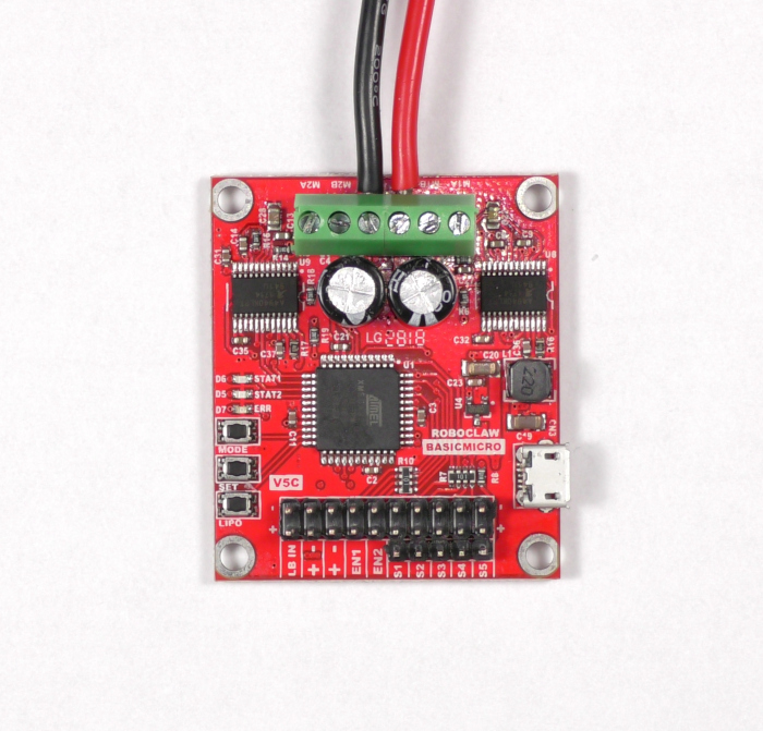
Figure 1: Power wired properly to the RobClaw.
3. Connect the USB cable between the RoboClaw and your computer.
4. Open Basicmicro Motion Studio. In the upper left hand corner of the application you should see a box labeled “Attached Devices”. Your RoboClaw should appear here, if not check your USB connection and check that power has been properly applied to the RoboClaw. If your device is listed, select it and click “Connect Selected Unit”. The Stat1 led on the RoboClaw will begin flashing. Once you’ve verified that you can connect the RoboClaw to Motion Studio click “Disconnect Selected Unit” to stop communication with the RoboClaw.
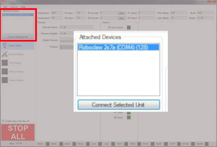
Figure 2: The location in Motion Studio where a RoboClaw is connected.
5. Disconnect power from the RoboClaw by removing the positive lead and then the negative lead. You must do it in this order or you will damage the RoboClaw. If your battery has a switch you can simply open the switch to disconnect power.
6. Now we will begin wiring the motors to the RoboClaw. Locate the terminals labeled M1A and M1B. Loosen the screws on these terminals before you begin wiring. Wire the first motor to the terminals labeled M1A and M1B by placing one end of the bare wire in each terminal and tightening the screws with your screwdriver until the connection is snug. Note that the order of wiring does not matter for the first motor.
7. The second motor is wired to the terminals labeled M2A and M2B. The order of wiring does matter for this motor. Look at the first motor you wired and note what color wire you wired to the M1A terminal. Connect the same colored wire of the second motor to the M2A terminal. Lastly, connect the final wire of the second motor to the M2B terminal. Make sure that your motor wire connections are secure and do not come loose from the terminals.
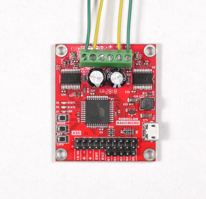
Figure 3: Two motors wired to the RoboClaw properly.
8. Reconnect power to the RoboClaw as done earlier.
9. Open Basicmicro Motion Studio again and reconnect the RoboClaw again by clicking “Connect Selected Unit”. Click on “PWM Settings” in the left-hand pane. Here we will test the motors to make sure they’re working. Find the box labeled “Control”. Slide the sliders for Motor 1 and Motor 2. The motors should turn when operating the sliders. Also check to ensure that the motors turn forwards when sliding the sliders up and backwards when sliding the sliders down. If the motors do not turn the proper direction you need to reverse the wiring of one or both motors.
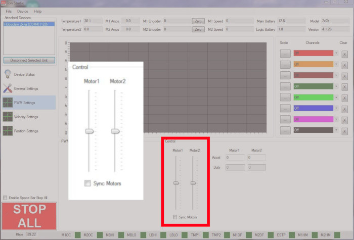
Figure 4: The motor sliders used to test both motors.
10. Disconnect the RoboClaw in Motion Studio and remove power from the RoboClaw as done earlier.
11. Now we will attach one channel of the receiver to the RoboClaw. Located the pin header labeled S1, this is where we will connect the output from the radio receiver. Also, using the receiver’s manual find the connection for the throttle channel. Using a servo cable connect the throttle channel to S1. Note that the connections at the receiver and RoboClaw are both polarized. On the RoboClaw the negative pin of S1 is towards the inside of the board. The polarity on the receiver varies by model and is labeled on some receivers.
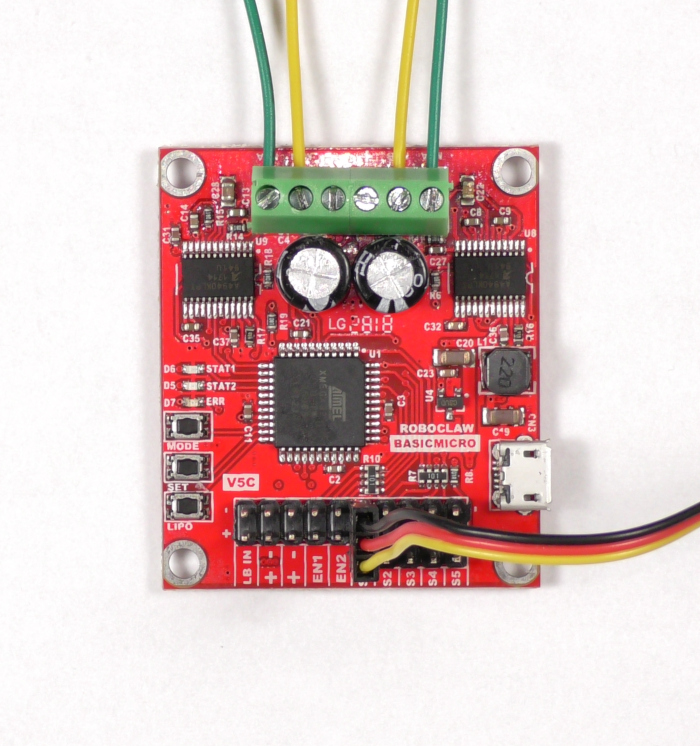
Figure 5: One RC channel connected.
RoboClaw BEC Powering the Receiver
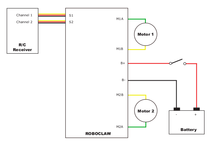
Figure 2: In this wiring configuation the 5V line is connected between the RoboClaw and receiver. The RobClaw powers the receiver.
Receiver with External Power
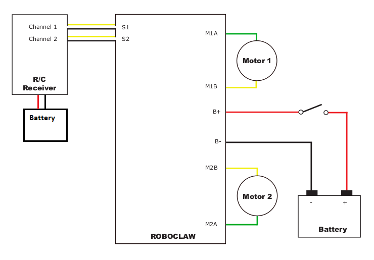
Figure 2: In this wiring configuration the receiver is powered extenally and the 5V line between the RobClaw and receiver has been removed.
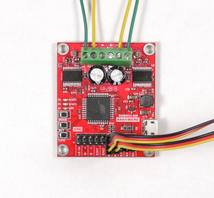
Figure 3: Two RC channels connected to the RoboClaw.
12. Turn on your radio transmitter.
13. Reconnect power to the RoboClaw and open Basicmicro Motion Studio. Reconnect the RoboClaw in Motion Studio as done previously.
14. If you need to bind your receiver please do it now while power is applied.
15. It’s time to configure the RoboClaw from Basicmicro Motion Studio. The first order of business is to set the control mode for the controller. Click on “General Settings” in the left-hand pane of Ion Studio, a new screen of options will be presented to you. Locate the Settings panel and set the Control Mode to “RC”.
16. Now look at the RC/Analog Options panel. There are two settings here that are relevant to our use case. The first is mixing, this is what allows us to use the board to control the motors in a differential fashion. Check the “Mixing” box to enable mixing. Exponential is another option that you can enable. This changes the proportion of stick movement to motor movement from dead center to the outer edge of the stick range. However, this is not mandatory and is simply a user preference.
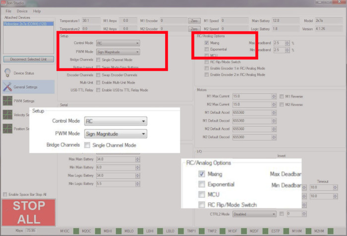
Figure 6: Location to set the mode and RC options.
17. Save the settings to the RoboClaw by going to the menu and selecting “Device” and then “Save Settings”.
18. Test the throttle channel channel by moving it up and down. The motors should respond to the throttle input.
19. Disconnect the RoboClaw in Ion Studio and remove power to the RoboClaw as you’ve done previously.
20. Located the pin header labeled S2. Connect the aileron channel of the receiver to S2 as you did with the throttle channel. Remember to observe proper polarity.

Figure 7: Two RC channels connected to the RoboClaw.
21. Ensure your radio transmitter is still on.
22. Reconnect power to the RoboClaw.
23. Test that the motors are responding properly to each radio channel input. Throttle input should cause both motors to turn in the same direction. Aileron input should cause the motors to turn in opposite directions.
Conclusion
You should now have a properly functioning system in which you can operate your differential drive system easily with your RC transmitter. Some builders with leave this as their final control scheme, while others will simply use this as a way to test their system in a rough way before moving on to some other control scheme. The choice is up to you.