Introduction
When using the RoboClaw in packet serial mode two or more RoboClaw motor controllers can be used together, each with independent control from a microcontroller. This App Note details the wiring and some example code to get this setup working.
Materials
(2) RoboClaw motor controllers
(1) Arduino Uno
(1) Adafruit Proto-Screwshield *
(2) motors, one for each RoboClaw
(2) batteries, one for each RoboClaw motor controller
(7) female jumper wires
(1) 4.7Kohm through hole resistor
(1) micro USB cable
(1) small screwdriver
(1) computer with BasicMicro Motion Studio installed
* Adafruit part link
Let’s get started!
1. Assemble the Arduino shield. Instructions for assembling the board can be found here.
2. Wire one motor and battery to each RoboClaw. Please follow this tutorial to step 10.
3. Disconnect power from each RoboClaw.
4. Remove one end of 6 jumper wires leaving a female connector on the other end. Tin the bare wire ends of each jumper wire with a small amount of solder. Be sure the wire ends are twisted together neatly with no strands of wire sticking out.
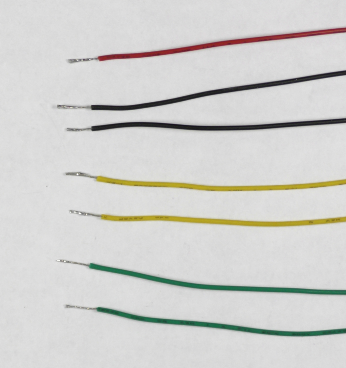
Figure 1: Image of properly tinned wire ends.
5. Remove both ends of the 7th jumper wire and tin both ends as in the previous step.
6. Solder one end of the 4.7Kohm resistor to one end of the jumper wire you removed both ends from.
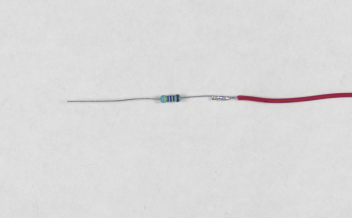
Figure 2: Image of resistor soldered to the 7th jumper wire.
7. Using the table below connect each RoboClaw to the Arduino shield. You’ll need to complete the wiring labeled in the table for each RoboClaw. The wires for each function from both RoboClaws are wired together in the appropriate screw terminal.
| Function | RoboClaw | Arduino Shield |
| Receive | S2 signal pin on each | Screw terminal 10 |
| Transmit | S1 signal pin on each | Screw terminal 11 |
| Ground | Encoder power (-) pin on each | Any ground terminal |
8. Connector the jumper with the resistor from screw terminal 10 of the shield to any 5V terminal on the shield. This is used to keep the line pulled high when there is no communication between the Arduino and the connected RoboClaws.
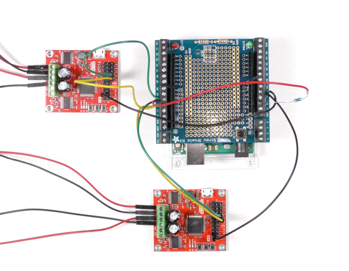
Figure 3: Both RoboClaws wired to the Arduino shield.
9. Reconnect power to each RoboClaw.
10. Connect one RoboClaw to your computer with the micro USB cable. Open BasicMicro Motion Studio and connect the RoboClaw as detailed in the App Note linked to in step two. Click on “General Settings” in the left-hand side of the application. Locate the “Setup” pane. In the dropdown for “Control Mode” select “Packet Serial”. Check the option for “Enable Multi-Unit Mode”. Now find the “Serial” pane. Using the table below set the address and baud rate specified. Once you’re done save the settings to the board by clicking “Device” in the menu at the top of the window and then clicking “Write Settings”. Repeat this process for the second RoboClaw, be sure to select the proper address for the second board. The address needs to be different for each board.
| RoboClaw | Address | Baudrate |
| #1 | 128 | 38400 |
| #2 | 129 | 38400 |
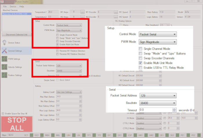
Figure 4: Location of the settings for packet serial operation.
11. Connect the Arduino to your computer with a USB cable. Download the RoboClaw library from here and add it to your Arduino library. Instructions for adding a library to Arduino can be found here.
12. Download the sketch for this App Note from here. Open the sketch and upload it to your Arduino.
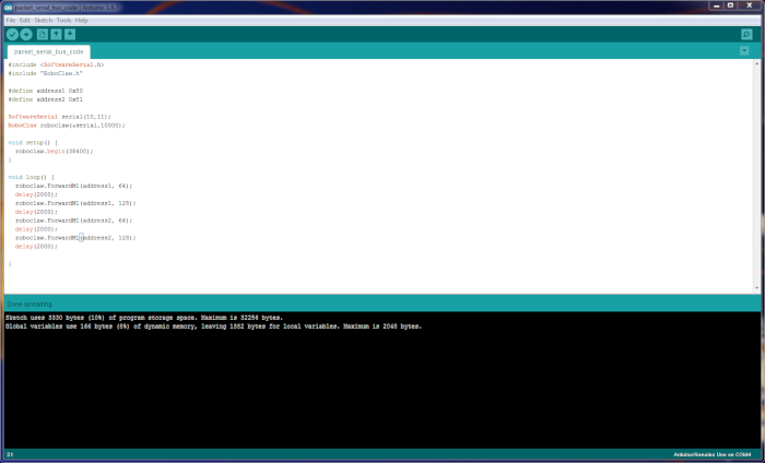
Figure 5: The demonstration sketch in the Arduino IDE.
13. Once the sketch starts running the motor on each RoboClaw should start and stop in an alternating fashion, one motor will run and then stop and then the motor attached to the second RoboClaw will run and then stop. If the system does not seem to running properly check that the serial connections are seated properly and not reversed. You may also need to reconnect each RoboClaw to Motion Studio and check that the baudrate for each controller is set to 38400bps and that each controller has the right hardware address.