Introduction
In this Application Note we’ll be wiring an analog joystick to the RoboClaw so that it can be used to control the speed and direction of two motors. This is a handy and intuitive way to control something like a tank style robot.
Materials
(1) RoboClaw motor controller
(1) Analog joystick *
(2) resistors
(1) soldering iron
(1) roll of solder
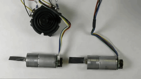
(2) motors
(1) battery for RoboClaw
(6) female jumper wires
(1) USB cable
(1) computer with BasicMicro Motion Studio installed
(1) small screwdriver
* Adafruit part link
Let’s get started
1. See this tutorial and follow the Application Note to step 10.
2. Be sure you’ve disconnected power from the RoboClaw.
3. Measure the resistance of the potentiometers on your joystick. Using a multimeter measure the resistance between the two outermost pins on the potentiometers of your joystick. Common potentiometer values are 5Kohm, 10Kohm and 20Kohm.
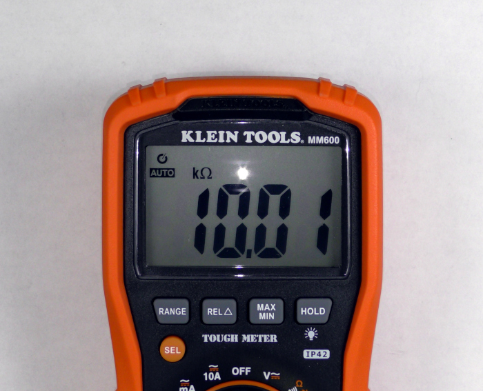
Figure 1
The resistance of a potentiometer measured with a multimeter.
4. Select the appropriate resistors. The table below can be used to select the appropriate resistors for common potentiometer values. If your potentiometer value is not listed below multiply the potentiometer value by 1.5 to get the resistor value needed.
| Potentiometer | Resistor |
| 5Kohm | 7.5Kohm |
| 10Kohm | 15Kohm |
| 20Kohm | 30Kohm |
5. Solder the resistors to the potentiometers. Tin the leftmost potentiometer pad with a small amount of solder. Then solder a resistor to the pad. Repeat this for the second potentiometer on the joystick.
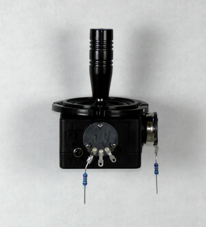
Figure 2
One resistor soldered to the leftmost pin on each potentiometer.
6. Prepare the jumpers for soldering. Cut one end of the jumper wires off leaving a female connector on the other end. Strip a small amount of insulation off the cut end and tin the end of each wire with a small amount of solder.
7. Solder the wires to the potentiometers. Tin the remaining pads on the two potentiometers. One by one solder the prepared wires to the potentiometer. Note that one wire on each potentiometer will need to be soldered to the end of the resistor previously soldered on to the potentiometer.
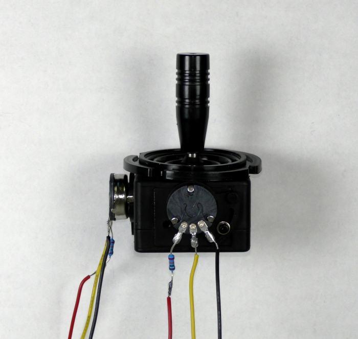
Figure 3
Female jumper wires soldered to each potentiometer.
8. Wire the joystick to the S1 and S2 headers. Locate the S1 and S2 headers, this is where the potentiometers of the joystick will be wired. The pin of each potentiometer with the resistor is wired to the (+) pin of the header, the rightmost pin is wired to the (-) and the middle pin is wired to the signal pin. Consult the table below for the proper wiring. Repeat this process with the second potentiometer.
| Potentiometer | RoboClaw |
| Left contact (side with resistor) | + pin (middle pin on header) |
| Middle contact | signal pin (pin closest to outside edge of board) |
| Right contact | – pin (pin on inside edge of board) |
9. Reconnect power to the RoboClaw as you’ve done previously.
10. Open BasicMicro Motion Studio. Connect the RoboClaw by clicking “Connect Selected Unit”. Next select “General Settings” from the left-hand side of the application window. Now find the section labeled “Setup”. Select “Analog” in the dropdown labeled “Control Mode”. Save the setting to the board by selecting “Device” in the menu at the top of the windows and clicking on “Write Settings”. The RoboClaw is now configured in Analog Mode.
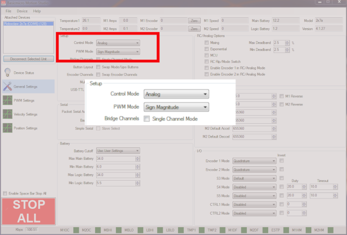
Figure 4
Location of analog mode setting in BasicMicro Motion Studio.
11. Test the operation of the joystick by moving it left and right and up and down. Each direction should turn a separate motor and each side of a given direction should turn the motor in a different direction. The speed of each motor should vary by how much the joystick is moved in each direction. If this does not work check your wiring again against the table in section 8 of this App Note. Be sure that the middle wire of each potentiometer is attached to the signal pin (pin closest to board edge) of the S1 and S2 headers.