
A PID controller is a feedback loop that keeps a value, such as motor speed or position, at a commanded setpoint by continuously correcting the error between the setpoint and the measured value. Motor controllers like the RoboClaw use PID control with encoder feedback to hold speed and position accurately under changing loads.
Motor controllers like the RoboClaw and MCP series use feedback from sensors, usually encoders, to maintain the speed and position of motors. Internally, a system called a PID controller keeps these values at their setpoints. This guide covers what a PID controller is, why it matters, how each of its three terms works, and how motor controllers put it to use.
What Is a PID Controller?
A PID controller is part of a feedback loop used to keep a value in a system at a commanded target. The target is called the setpoint, the value actually observed is the measured value, and the difference between the two is the error. In a motor controller, a PID controller keeps motor speed or position where the user commands it. Outside conditions, such as an increasing load on a motor, cause the measured value to drift away from the setpoint. The PID controller automatically corrects for these changes and brings the motor speed or position back to the commanded value.
Why Use a PID Controller?
In a system like a robot it is desirable, and sometimes essential, to maintain values like motor speed or motor position for the system to operate properly. Wheeled robots need consistent, accurate speed to drive straight, turn properly, and account for changes in traction. Robotic arms need accurate, repeatable positioning to locate, grab, and move objects. A PID controller maintains these values over time without constant manual correction.
How a PID Controller Works
A PID controller looks at the error between the measured value and the setpoint and works to bring that error as close to zero as possible. Internally it computes three separate corrections from the error and adds them together to produce the output. The three corrections are the proportional, the integral, and the derivative, and each has a numerical gain value that sets how strongly it acts on the system. Tuning a PID controller means choosing those three gain values.
In plain terms, the controller output is the sum of the three corrections:
output = (P x current error)
       + (I x accumulated error over time)
       + (D x rate of change of the error)
The Proportional Term
The proportional term looks at the current error and corrects in proportion to its size: the larger the error, the stronger the correction. A proportional gain that is too high causes the system to react too quickly and overshoot the setpoint, leading to a system that oscillates. Too low, and the system responds sluggishly and never quite corrects the error.
The Integral Term
The integral term accumulates the error over time. Its job is to eliminate steady-state error: the small, persistent offset that the proportional term alone can never remove, because a proportional correction shrinks as the error shrinks. Any long-term trend in the error is compensated for by the integral correction. As with the proportional term, an integral gain that is too high causes overshoot and oscillation around the setpoint. Too low, and the system is slow to remove steady-state error.
The Derivative Term
The derivative term responds to the rate of change of the error, which lets it anticipate where the error is heading. If the proportional and integral corrections are about to overshoot the setpoint, the derivative dampens the response and helps prevent the overshoot and the oscillation that follows. The derivative also amplifies noise in the feedback signal, so a gain that is too high can slow the system’s response and introduce oscillation of its own. In most motor control applications a derivative gain of zero is sufficient; it is only needed when stable control cannot be achieved with the proportional and integral terms alone.
PID Gain Effects at a Glance
The table below summarizes how each term behaves when its gain is set too low or too high.
| Term | Too Low | Too High |
|---|---|---|
| Proportional (P) | Sluggish response; the error is never fully corrected. | Overshoot and oscillation around the setpoint. |
| Integral (I) | Steady-state error is removed slowly, if at all. | Overshoot and oscillation; the accumulated correction keeps pushing after the error is gone. |
| Derivative (D) | Little damping, so overshoot from P and I goes uncorrected. Zero is normal for most motor applications. | Slowed response and noise-driven oscillation. |
How Motor Controllers Use PID
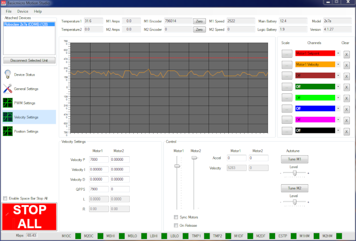
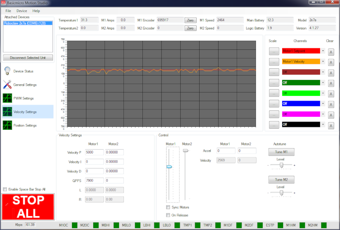
RoboClaw and MCP series motor controllers run PID control onboard, using feedback from quadrature or absolute encoders. The control loops run at 300 Hz, updating the motor output every 3.3 milliseconds. Two kinds of control are available. Velocity control uses a velocity PID paired with a QPPS value, the motor’s maximum speed in encoder counts per second, to hold a commanded speed. Position control moves the motor to a commanded position and can run as a PD controller, a full PID controller, or a cascaded PIV controller that combines a velocity loop with a position loop.
The PID values are set in BasicMicro Motion Studio, either automatically with the Auto Tune function, covered in Auto Tuning with Motion Studio, or by hand, and they can also be set from packet serial commands. Once tuned, the values are saved to the controller’s onboard EEPROM and reload automatically every time the unit powers up. Velocity and position error limits can also be set: if the error between the setpoint and the measured value grows past the limit, the controller treats it as a fault condition and stops the motors, protecting against runaway motion from a failed encoder or a jammed mechanism.
Next Steps
The velocity and position PID settings are covered in detail in Velocity Settings in Motion Studio and Position Settings in Motion Studio, and Velocity and Position Error Limits explains how the error limits protect a system when control is lost.


