
Encoders give the RoboClaw the feedback it needs for accurate speed and position control. This guide shows how to wire a Pololu 25D metal gearmotor with a built-in quadrature encoder to a RoboClaw motor controller and verify that the encoder counts correctly in BasicMicro Motion Studio.
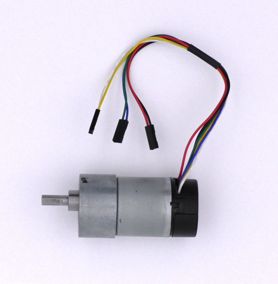
The RoboClaw uses encoders as part of a feedback system that allows control of motor speed and position. Many motors include encoders as part of the assembly. In this Application Note we’ll be wiring up and testing a popular gearmotor from Pololu that has a built-in quadrature encoder: the 25D metal gearmotor. The instructions in this Application Note apply to all of the motor and quadrature encoder combinations in this series.
What You Need
- 1× RoboClaw motor controller
- 1× Battery or power supply for the RoboClaw
- 2× Pololu 25D metal gearmotors with encoders
- 4× Male to female jumper wires
- 1× Computer with BasicMicro Motion Studio installed
- 1× USB A to micro B cable
- 1× Small screwdriver
- 6× 2 pin 0.1″ plastic header connectors
How Quadrature Encoders Work
Beyond basic wiring of the encoder there are a few things to know about how encoders work. As you may have noticed, each encoder has two outputs. All quadrature encoders have two output channels, often labeled A and B. The signal coming from these outputs is a pulse train of square waves. Each pulse corresponds to one mark on the encoder disk, and this is what is counted by the quadrature decoder on the RoboClaw. The outputs from both channels are out of phase from each other by 90 degrees. The decoder determines the direction of rotation by looking at which channel’s pulse train leads the other.
Quadrature encoders are rated by the number of output pulses per revolution. This is the number of pulses that will be output every time the shaft completes one full turn. The encoder used in this Application Note provides 48 counts per revolution of the motor shaft, and coupled with the gearbox it outputs 979.62 counts per revolution of the output shaft. The higher the number of counts per revolution, the more precise the control of the gearmotor, which means that the motor controller will be able to more precisely control the position or velocity of the motor.
A problem that will often be encountered when dealing with encoders is electrical noise. Noise can appear on the encoder output lines due to external signals that are nearby or due to improper filtering at the encoder. When noise appears on an encoder output the decoder will often count noise spikes as encoder counts and cause problems with the motor controller maintaining velocity and position control. Keeping the encoder lines away from other wires, particularly those carrying large amounts of power or rapidly changing signals, helps to reduce noise, as does keeping the encoder output wires as short as possible.
Encoder Wire Color Code
The Pololu gearmotor uses the standard six wire encoder hookup: two motor power wires, two encoder power wires, and two encoder signal wires. The table below is the wire color code for the harness. The same six functions appear on any motor with a built-in quadrature encoder, though the colors vary by manufacturer.
| Color | Function | Connector Pair |
|---|---|---|
| Red | Motor positive | Motor power |
| Black | Motor negative | Motor power |
| Green | Encoder ground | Encoder power |
| Blue | Encoder Vcc | Encoder power |
| Yellow | Encoder channel A | Encoder signal |
| White | Encoder channel B | Encoder signal |
Changing the Connectors on the Wiring Harness
The Pololu gearmotor comes with a 6 pin connector on its wiring harness. To make connecting the various wires to the appropriate locations on the RoboClaw easier, the wiring will be divided up into 3 pairs of wires and a 2 pin connector added to each pair.
-
Identify the three wiring pairs using the wire color code table above. Each pair will be placed into its own 2 pin connector.
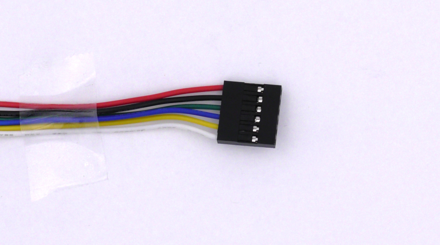
Figure 2: The wiring harness with the stock 6 pin connector. -
Remove the existing connector from the wiring harness by lifting up the small tab holding in each wire and pulling the wires out one by one.
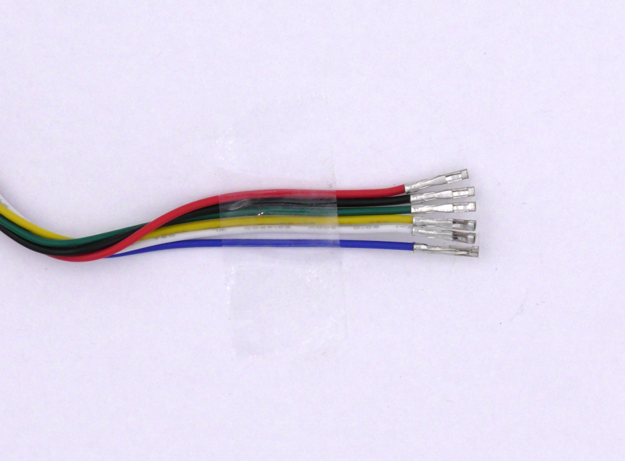
Figure 3: The wiring harness with the connector removed. -
For each pair of wires in the table, insert the wires for the pair into an empty 2 pin connector. When inserting a wire, orient the open side of the crimp connector facing the hole in the flat side of the connector. If the wire has been inserted correctly it will click into place and will not pull out of the connector. Repeat this process for all of the pairs in the harness.
Double-check each pair against the wire color code table before connecting anything. Placing the wrong wires together in a connector, such as a motor power wire paired with an encoder wire, can damage the encoder or the RoboClaw.
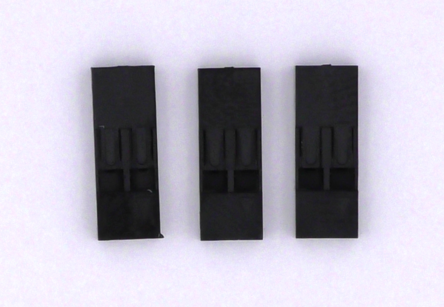
Figure 4: The connectors before installation. 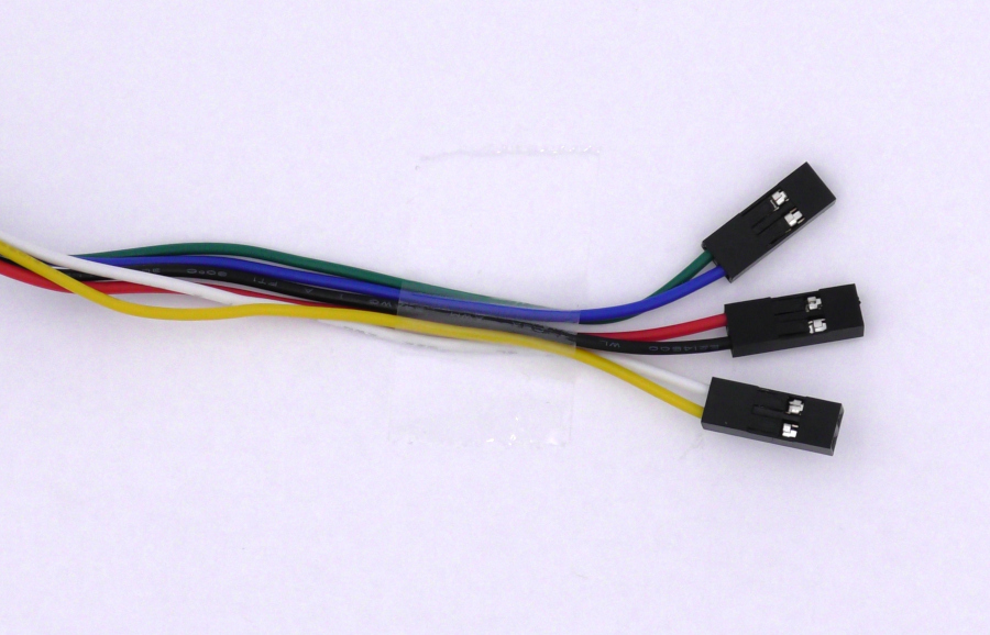
Figure 5: The wiring harness with connectors on the appropriate pairs.
Wiring the Encoders to the RoboClaw
Disconnect power from the RoboClaw before wiring the encoders.
-
Locate the EN1, EN2 and encoder power headers on the RoboClaw. Each encoder has two power wires and two output wires for a total of 4 wires that need to be connected to the RoboClaw. Wire the encoder according to the table below. The encoder of each motor will need to be wired to the correct encoder header: motor channel M1 uses EN1 and motor channel M2 uses EN2.
Motor Wire Function RoboClaw Board Red Motor positive M1A/M2A terminal Black Motor negative M1B/M2B terminal Green Encoder ground (-) pin on encoder power header Blue Encoder Vcc (+) pin on encoder power header Yellow Encoder A output EN1/EN2 header inside pin White Encoder B output EN1/EN2 header outside pin 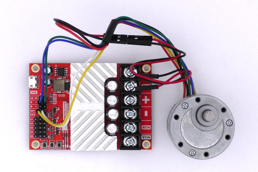
Figure 6: Completed wiring for one encoder channel. The above setup illustrates a test setup. Both motor wires will need to be secured properly before a final installation. Please see Proper Wire Termination for details.
-
If a second motor is present repeat the process. Remember to ensure the encoder is wired properly and is paired with the correct encoder channel.
-
Reconnect power to the RoboClaw.
-
Connect the USB cable between the RoboClaw and the computer and open BasicMicro Motion Studio. Select the RoboClaw in the box labeled “Attached Devices” and click “Connect Selected Unit”. Click on “PWM Settings” in the left-hand pane. Use the sliders labeled “Motor 1” and “Motor 2” to move the motors forwards and backwards. Moving the slider up should move the motor forwards and down backwards. If the encoders are working properly the “M1 Encoder” and “M2 Encoder” values at the top of the window should increment when the motor moves in the forwards direction and decrement in the backwards direction.
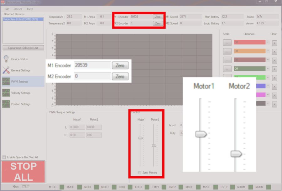
Figure 7: BasicMicro Motion Studio encoder count and motor control testing. -
If the encoder counts don’t correspond to the motor direction, the A and B channels are backwards. Power down the RoboClaw and reverse the connections on either the EN1 or EN2 header depending on which encoder isn’t working properly. The reason these two connections need to be reversed is that the RoboClaw uses the signals from both encoder channels to determine which direction the motor is rotating. If channel A and channel B of the encoder are reversed the motor controller thinks the motor is rotating in the opposite direction than it is physically rotating. If the encoder count doesn’t change at all in Motion Studio check to see if you’ve reversed the power connections for the encoder. If the encoder power has been reversed it’s possible that the encoders are now damaged.
Reading Encoders with an Arduino
A microcontroller such as an Arduino can be used to read data from and about the encoders using the Basicmicro Arduino library. To install the library and learn its basics, see Using the RoboClaw Arduino Library. For wiring an Arduino to the RoboClaw and configuring packet serial mode, see Simple Arduino Control of the RoboClaw.
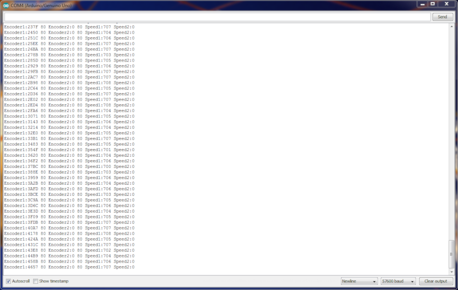
The functions used in the sketch below are:
uint32_t ReadEncM1(uint8_t address, uint8_t *status=NULL, bool *valid=NULL);
uint32_t ReadEncM2(uint8_t address, uint8_t *status=NULL, bool *valid=NULL);
uint32_t ReadSpeedM1(uint8_t address, uint8_t *status=NULL, bool *valid=NULL);
uint32_t ReadSpeedM2(uint8_t address, uint8_t *status=NULL, bool *valid=NULL);
These functions return the encoder count and speed as integers. You simply need to pass them the address of the RoboClaw in use and, optionally, variables to hold the status and valid values.
SoftwareSerial is only available on AVR-based boards such as the Uno and Nano, and it requires #include <SoftwareSerial.h> at the top of the sketch. For boards with additional hardware serial ports, see Using the RoboClaw Arduino Library for the hardware serial setup.
#include <SoftwareSerial.h>
#include <Basicmicro.h>

SoftwareSerial serial(10, 11); // RX (RoboClaw S2), TX (RoboClaw S1)
Basicmicro roboclaw(&serial, 10000);

// Must match the packet serial address set in Motion Studio
#define ADDRESS 128

void setup() {
  // Open the Serial Monitor port and the RoboClaw serial port.
  // The RoboClaw baudrate must match the packet serial baudrate
  // set in Motion Studio.
  Serial.begin(57600);
  roboclaw.begin(38400);
}

void loop() {
  uint8_t status1, status2, status3, status4;
  bool valid1, valid2, valid3, valid4;

  // Read all of the data from the RoboClaw before printing it.
  // This keeps the hardware serial interrupt from interfering
  // with reading data using software serial.
  int32_t enc1 = roboclaw.ReadEncM1(ADDRESS, &status1, &valid1);
  int32_t enc2 = roboclaw.ReadEncM2(ADDRESS, &status2, &valid2);
  int32_t speed1 = roboclaw.ReadSpeedM1(ADDRESS, &status3, &valid3);
  int32_t speed2 = roboclaw.ReadSpeedM2(ADDRESS, &status4, &valid4);

  if (valid1) {
    Serial.print("Encoder1:");
    Serial.print(enc1, DEC);
    Serial.print(" ");
    Serial.print(status1, HEX);
    Serial.print(" ");
  }
  if (valid2) {
    Serial.print("Encoder2:");
    Serial.print(enc2, DEC);
    Serial.print(" ");
    Serial.print(status2, HEX);
    Serial.print(" ");
  }
  if (valid3) {
    Serial.print("Speed1:");
    Serial.print(speed1, DEC);
    Serial.print(" ");
  }
  if (valid4) {
    Serial.print("Speed2:");
    Serial.print(speed2, DEC);
  }
  Serial.println();

  delay(100);
}
Tuning the Motors and Encoders
After wiring the encoders and checking to make sure they’re working properly, the motor and encoder combination can be tuned in BasicMicro Motion Studio. Auto Tuning with Motion Studio covers the auto-tune function. If precise position and speed control isn’t required for a project, tuning can be skipped. However, if precise control of speed and/or position is needed, the motor and encoder combination must be tuned. Motion Studio provides an auto tune function to take care of this or you can manually do this yourself.
Next Steps
With the encoders wired and verified, the next steps are tuning the motors and reading the encoders from your own code:
- Using Encoders with the Arduino Library: reading and using encoder data in Arduino sketches.
- Basicmicro Arduino library examples on GitHub: complete example sketches for the library’s commands.


