Introduction
Why Proper Termination Matters
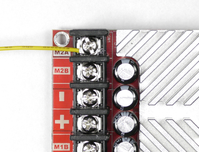
Figure 1: This photo shows the wrong way of wiring an open screw terminal. The wire comes in from the right side and strands of wire are exposed.
Solutions
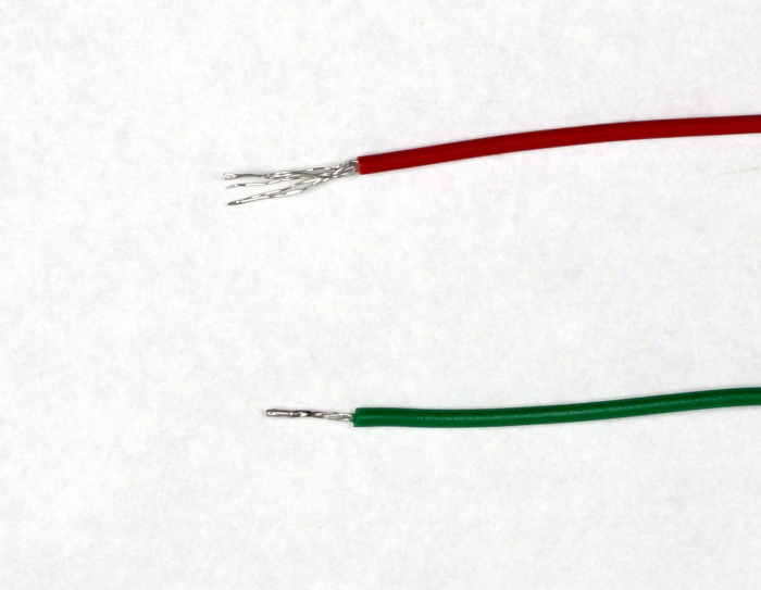
Figure 2: The red wire is untinned and the green wire is tinned.
The second solution is to use crimp on terminals. These can be used with the open type screw terminals. They come in two broad types: the forked type, knows as spade terminals, and ones with a closed ring. If you only occasionally remove connections to the motor controller a ring type terminal works well. A spade type termial is useful when connecting and disconnecting connections on a regular basis. You will need the appropriate terminal connector and a matching set of crimpers to add these to your bare wires. Below is a table of suggested ring terminals based on wire size along with their Digi-Key part numbers.
| Wire Size | Terminal |
| 10-14awg | 277-11158-ND |
| 8awg | 277-11162-ND |
| 6awg | A28245TR-ND |
Figure 3
Table of suggested ring terminals based on wire size. Diki-Key part numbers and links are included.
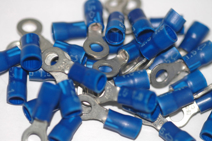
Figure 3: An example of ring terminals.
Photo by Mataresephotos / Wikipedia Commons
If you do need to use a bare wire connection on open type screw terminal there is a right way and a wrong way to do connect it. The right way is to loop the wire in a clockwise direction before you tighten the screw. This allows the wire to snug up as the screw is tightened. If you loop it in the counter-clockwise direction the wire will not be as secure and can also fray causing shorts as mentioned earlier. Be sure to twist the wire ends together before you loop the wire around the screw.
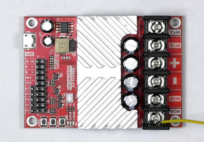
Figure 4: This photo shows the proper wiring for an open screw terminal. The wire comes in from the left side and is carried around by the rotation of the screw.<