Introduction
In analog mode an analog input applied to the signal lines of headers S1 and S2 can be used to control the speed and direction of both motor channels. The analog voltage can come from a potentiometer or an analog joystick.
Control via Potentiometers
Materials
(1) RoboClaw motor controller
(2) potentiometers
(2) appropriate resistors (see text below)
(1) soldering iron
(1) roll of solder
(2) motor(s)
(1) Battery for RoboClaw
(6) jumper wires with female ends
(1) USB cable
(1) Computer with BasicMicro Motion Studio installed
(1) small screwdriver
1. See this tutorial and follow the Application Note to step 10.
2. Be sure you’ve disconnected power from the RoboClaw.
3. Select the appropriate resistor. The table below list the resistor required for common potentiometer values. You’ll need two of these, one for each potentiometer.
| Potentiometer | Resistor |
| 5Kohm | 7.5Kohm |
| 10Kohm | 15Kohm |
| 20Kohm |
30Koh m |
4. Solder a resistor to the left-hand terminal of each potentiometer. In this example we are using 10K potentiometer, as per the table this requires the use of a 15K ohm resistor.
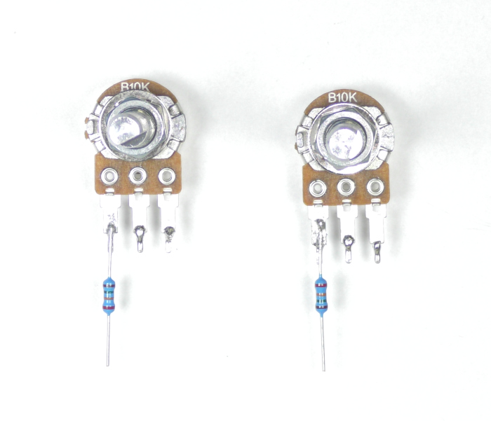
Figure 1: Resistor soldered on potentiometer.
5. Cut one end off of each female jumper leaving one female connector on the other end. This will be used to connect to the pin headers on the RoboClaw.
6. Tin the bare wire end of each jumper wire with a small amount of solder.
7. Solder the bare end of one wire to each potentiometer contact. Color code them for ease of use. One of the wires will have to be soldered to the end of the resistor instead of the contact on the potentiometer.
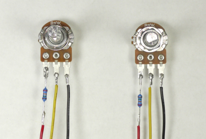
Figure 2: Wires soldered to potentiometer.
8. Now we’ll connect the jumpers to the RoboClaw. Locate the S1 header on the RoboClaw board, this is where we’ll connect the first potentiometer. Use the table below to wire the potentiometer.
| Potentiometer | RoboClaw |
| Left contact (side with resistor) | + pin (middle pin on header) |
| Middle contact | signal pin (pin closest to outside edge of board) |
| Right contact | – pin (pin on inside edge of board) |
9. Repeat the above steps for the second potentiometer, connecting it to the S2 header pins.
Figure 3: Potentiometer connected to the RoboClaw S1 and S2 header.
10. Set each potentiometer to the middle of their range. This allows the RoboClaw to calibrate the center point.
10. Reconnect power to the RoboClaw.
11. Open BasicMicro Motion Studio and connect the RoboClaw as you’ve done earlier. Click on General Settings on the left-hand side of the windows. Now find the Setup pane. Click the dropdown labeled Control Mode and select Analog.
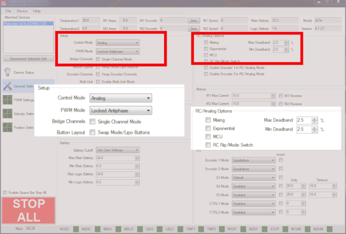
Figure 4: BasicMicro Motion Studio analog mode and settings.
12. To save your settings to the RoboClaw select Device from the menu at the top of the window and then click on Write Settings.
13. Test the operation of the motor(s) via the potentiometers. One side of the potentiometer’s directions should be reverse and the other forward. Speed should ramp up and down as the potentiometer is rotated.
Control via Analog Joystick
Materials
(1) RoboClaw motor controller
(1) Adafruit analog thumb joystick Link to product
(1) 7.5Kohm resistor
(4) jumper wires with female ends
(1) soldering iron
(1) solder
(2) motor(s)
(1) Battery for RoboClaw
(1) micro USB cable
(1) computer with BasicMicro Motion Studio installed
(1) small screwdriver
1. See this tutorial and follow the Application Note to step 10.
2. Be sure you’ve disconnected power from the RoboClaw.
3. Assemble the joystick by soldering the potentiometer assembly to the breakout board. Each pin that passes through the board must be soldered. Complete the assembly by pushing the thumb pad on to the white protruding stick.
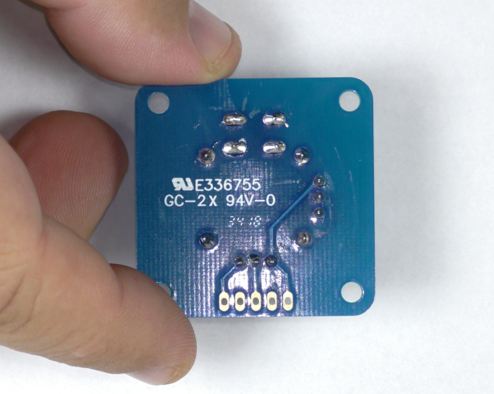
Figure 1: Back of analog joystick breakout board showing soldered pins.
4. Cut one end off of each of the 4 jumper wires, leaving a female connector on the uncut end.
5. Tin the bare wire ends of the 4 jumper wires with solder.
6. Tin the Vcc, Xout, Yout and GND pads of the breakout board with a small amount of solder.
7. Solder the 7.5K ohm resistor to the Vcc pad.
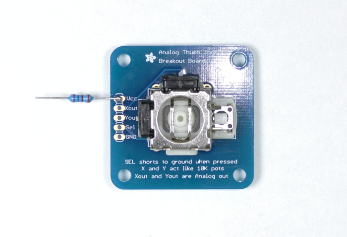
Figure 2: Resistor soldered to the Vcc pad.
7. Carefully solder each wire to the correct pad on the breakout board. One wire will have to be soldered to the end of the resistor.
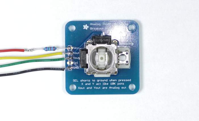
Figure 3: Wires soldered to their respective pads on the breakout board.
8. Now we will begin connecting the joystick up to the RoboClaw. Located the S1 and S2 headers on the RoboClaw board, this is where we will be making out connections.
| Joystick board | RoboClaw |
| Vcc | + pin of S1 header (middle pin on header) |
| Xout | signal pin of S1 header (pin closest to outside edge of board) |
| GND | – pin of S1 header (pin on inside edge of board) |
| Yout | signal pin of S2 header (pin closest to outside edge of board) |
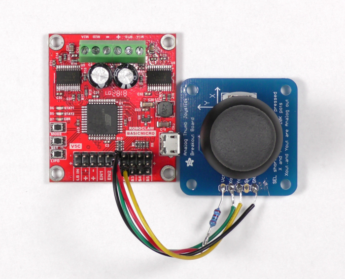
Figure 4: The analog joystick wired to the RoboClaw.
9. Reconnect power to the RoboClaw.
10. Open BasicMicro Motion Studio and connect the RoboClaw as you’ve done earlier. Click on General Settings on the left-hand side of the windows. Now find the Setup pane. Click the dropdown labeled Control Mode and select Analog.
Figure 5: BasicMicro Motion Studio analog mode and settings.
11. To save your settings to the RoboClaw select Device from the menu at the top of the window and then click on Write Settings.
12. Test the operation of the motors with the joystick. Moving the joystick left or right should operate one motor, the direction of rotation will depend on the direction of the joystick. Moving the joystick up or down should operate the other motor, once again the direction will determine which way the motor spins. If you move the joystick in a circular motion both motors should run at the same time as there is input to the RoboClaw on both channels.
Conclusion
You’ve now seen how the RoboClaw can be controlled with an analog input device. This is a simple and handy way of controlling a robot and can be used for testing or for your final build.