Introduction
The RoboClaw features a set of onboard leds that are used to indicate problems with the controller and with your hardware. The leds indicate three classes of problems: faults, warnings and notices.
LEDs
The status LEDS are located along the edge of the board right next to the buttons. The LEDS are labeled ERR, STAT1 and STAT2.
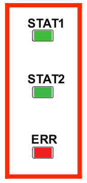
Figure 1
A diagram showing the status leds used to indicate problems with the RoboClaw.
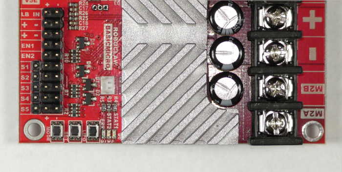
Figure 2
The status LEDs as found on the board.
Faults
The first class of errors are faults. There are unique led patterns for each of the faults listed in the table below.
| LED Indication | Condition | Controller Action |
| All three LEDS lit | E-Stop | Motors are stopped by braking. |
| Error LED blinks once with short delay. Other LEDs off. | Temperature over 100C | Motors freewheel while condition exists. |
| Error LED blinking twice. STAT1 or STAT2 indicates which channel. | Driver fault | Motors freewheel. Damage detected. |
| Error LED blinking three times. | Logic battery high | Motors freewheel until reset. |
| Error LED blinking four times. | Logic battery low | Motors freewheel until reset. |
| Error LED blinking five times. | Main battery high | Motors are stopped by braking until reset. |
Warnings
Warnings are the second class of errors. In the cases of warning conditions motor power is either limited or fully stopped depending on the warning. With warnings the Error LED stays lit to alert you to the problem. There are not unique codes for each warning condition.
| LED Indication | Condition | Controller Action |
| Error LED lit while condition is active. | Temperature over 85C | Motor current is recalculated based on temperature. |
| Error LED lit while condition is active. | Over current | Motor power is automatically limited. |
| Error LED lit while condition is active. | Main battey high | Motors are stopped by braking while condition exists. |
| Error LED lit while condition is active. | Main battery low | Motors freewheel while condition exists. |
| Error LED lit while condition is active. | M1 or M2 home | Motor is stopped and encoder is reset to 0. |
Notices
The third class of errors is the notice. Currently there is only one problem that will trigger a notice.
| LED Indication | Condition | Controller Action |
| All 3 LEDs cycle on and off in sequence after power up. | RoboClaw is waiting for new firmware | RoboClaw is in boot mode. Use BasicMicro Motion Studio to clear condition. |
Troubleshooting Current
The RoboClaw will reduce power to one or both motors if an overcurrent condition occurs. A multimeter can be used to check the current being pulled by your system. You can also check the amount of current being pulled by each motor in BasicMicro Motion Studio. Choose “PWM Settings” in the left hand pane, from here you can operate the motors via the sliders and view the current for each motor at the top of the window. Another thing to check are the maximum current settings in BasicMicro Motion Studio. These can be viewed by selecting “General Settings” from the left-hand side of the windows and then finding the “Motors” pane. The setting for one or both motors may be set too low for your application. Things to look out for are driving too heavy of a load or using motors that aren’t suitable for the motor controller you’ve selected. These problems can be solved by changing the load applied to the motors, changing out your motors for more suitable one or buying a motor controller that will tolerate the current drawn by your current setup.
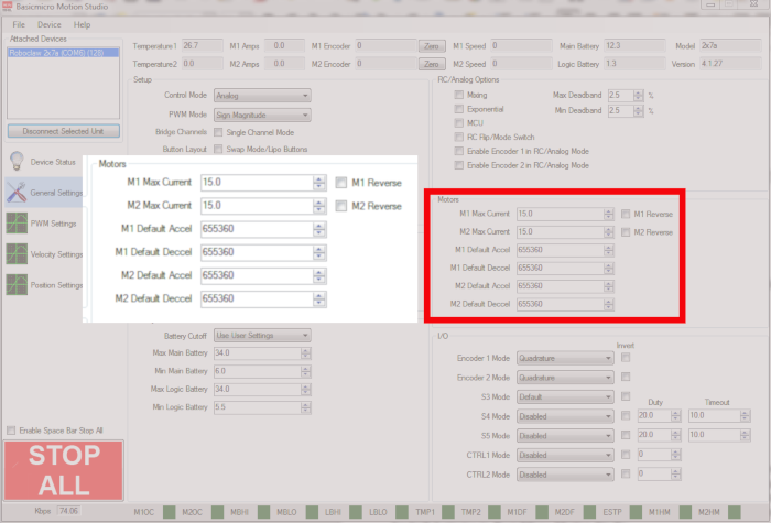
Figure 3
This image shows where the motor current settings are located in BasicMicro Motion Studio.
Troubleshooting Voltage
Voltage errors can occur when the main battery voltage is too high or too low. The same problem can present itself with the logic battery if one is being used. You can use a multimeter to check the voltage of either battery. If the voltage of either battery is within bounds for operation with the RoboClaw you will also need to check the battery settings for both batteries in BasicMicro Motion Studio. The main battery voltage and logic battery voltage can also be seen after you have connected the RoboClaw in BasicMicro Motion Studio. At the top of the windows are entries that display system voltages.
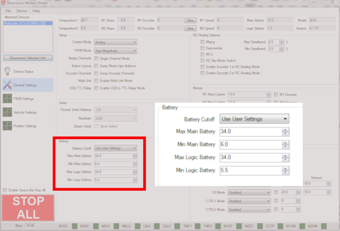
Figure 4
This image shows where the battery volatge settings are for both the main battery and the logic battery.
Troubleshooting Temperature
The RoboClaw will indicate a temperature warning at 85C[185F] and a temperature fault at 100C[212F]. The temperature can be read via serial commands or directly in BasicMicro Motion Studio at the top of the windows. Most often a temperature error is related to putting too much of a load on the controller. As with troubleshooting current problems you can reduce the load on your motors, change out motors or buying a larger motor controller. However there are also several other sources of temperature problems. If the ambient temperature is too high this can create problems with cooling on the RoboClaw. Also, for boards with a fan onboard, problems with the fan can lead to inadequate cooling of the board.
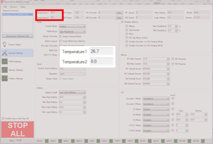
Figure 5
This image shows where the RoboClaw’s temepature is displayed in BasicMicro Motion Studio.
Conclusion
You should now understand how the RoboClaw’s LEDs are used to indicate problems with your robot. You have also seen that the majority of these problems are isolated to the power supplies for the RoboClaw and motors used with it.