Introduction
In standard serial mode the RoboClaw accepts byte commands from any microcontroller that can send them over a serial connection. The Arduino is a quick and easy way to test this functionality out or for final use in a robotics project. This App Note will cover the wiring, configuration and a test sketch for the Arduino.
Materials
(1) RoboClaw motor controller
(2) motors
(1) battery for RoboClaw
(1) Arduino board
(2) male to female jumpers
(1) small screwdriver
(1) USB cable for the Arduino
(1) micro USB cable for the RoboClaw
(1) computer with BasicMicro Motion Studio installed
Let’s get started
1. Follow this tutorial to step 10.
2. Disconnect power from your RoboClaw if you haven’t already done so.
3. Wire the Arduino and RoboClaw together with jumper wires using the table below as a reference.
| Function | Arduino | RoboClaw |
| Transmit | Pin 11 | S1 singal pin (pin closest to edge of board) |
| Ground | Any Arduino ground | Ground pin on S1 header (pin closest to inside of board) |
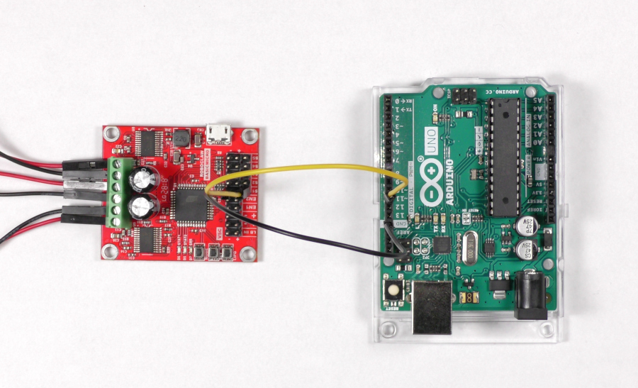
Figure 1: Image of the Arduino and RoboClaw wired together.
4. Reconnect power to your RoboClaw.
5. Open BasicMicro Motion Studio and connect your RoboClaw as done in the tutorial linked in to step 1. On the left-hand side of the application click on “General Settings”. In the pane labeled “Setup” set the control mode to “Simple Serial”. Now move down to the pane labeled “Serial” and set the baudrate to “38400”. Save the setting to the board by selecting “Device” from the menu and selecting “Write Settings”. Finally disconnect the RoboClaw in Motion Studio.
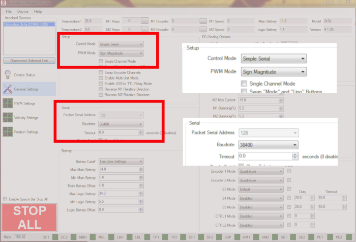
Figure 2: Configuring standard serial mode in Motion Studio.
6. Download the sketch for this App Note from here. Upload the sketch to your Arduino.
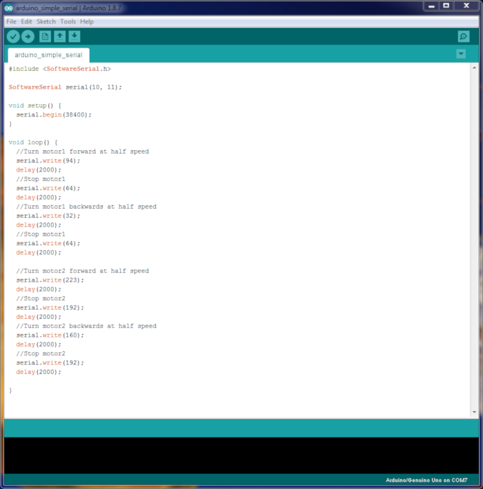
Figure 3: The sketch in the Arduino IDE.
7. Once the sketch starts running motor 1 should run in the fowards direction, pause and then run in the backwards direction. The process then repeats for motor 2. If you run into a problem check that there is a ground connection between the RoboClaw and Arduino and that there is a solid connection between pin 11 of the Arduino and the S1 header signal pin.
Explanation of the Sketch
Step seven explains how the sketch should run the motors. In the sketch only one function is called when communicating with the RoboClaw:
serial.write()
In standard serial mode the RoboClaw accepts single bytes to control both motor channels. The “write” function of the serial object does just this given a valid value between 0 and 255. The RoboClaw maps the byte value to speed and direction as shown in the table below.
| Value | Function |
| 0 | Shuts down channels 1 and 2 |
| 1 | Channel 1 full reverse |
| 64 | Channel 1 stop |
| 127 | Channel 1 full forward |
| 128 | Channel 2 full reverse |
| 192 | Channel 2 stop |
| 255 | Channel 2 full forward |
Communication Issues in Standard Serial Mode
When sending command bytes to the RoboClaw from a microcontroller there is no error checking or acknowledgement that a byte has been received. This means that if a byte is sent and not recived this is no indication that anything has gone wrong. To work around this send the byte to set the motor speed and direction in a periodic and repeating manner. Once every 100ms is a good starting point as a motor cannnot respond to changes much faster than that.