
An Arduino can control a RoboClaw motor controller over a packet serial connection using the Basicmicro Arduino library. Two jumper wires carry the serial signals, Motion Studio sets the control mode, and a short sketch drives both motors. This guide covers the wiring, the configuration, and a complete example sketch.
This guide works with any dual channel RoboClaw motor controller. The RoboClaw is configured for packet serial mode, and the Arduino sends commands to it with the Basicmicro Arduino library. The wiring shown uses an AVR-based Arduino such as the Uno or Nano, which support the SoftwareSerial library used in the example sketch.
What You Need
- 1× RoboClaw motor controller
- 2× Brushed DC motors
- 1× Battery or power supply
- 1× Arduino board (an Uno or Nano for the wiring shown)
- 2× Male to female jumper wires
- 1× Small screwdriver
- 1× USB cable for the Arduino model used
- 1× USB A to micro B cable for the RoboClaw
- 1× Computer running Windows 10 or 11 with Motion Studio installed
Wiring the Power and Motors
-
Identify the positive and negative leads of the battery. Find the two screw terminals on the RoboClaw labeled + and – and loosen the screws. Attach the negative lead first by placing it in the loosened terminal and tightening the screw until the connection is snug, then repeat with the positive lead. The battery settings for the RoboClaw should be set according to Configuring RoboClaw Battery Settings.
Do not wire the power source backwards or the RoboClaw will be permanently damaged.
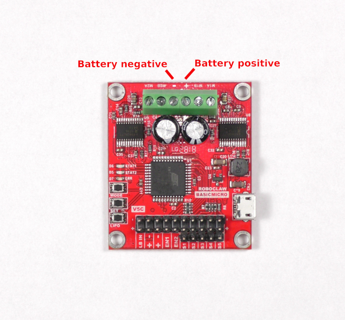
Figure 2: The positive and negative power terminals of the RoboClaw. 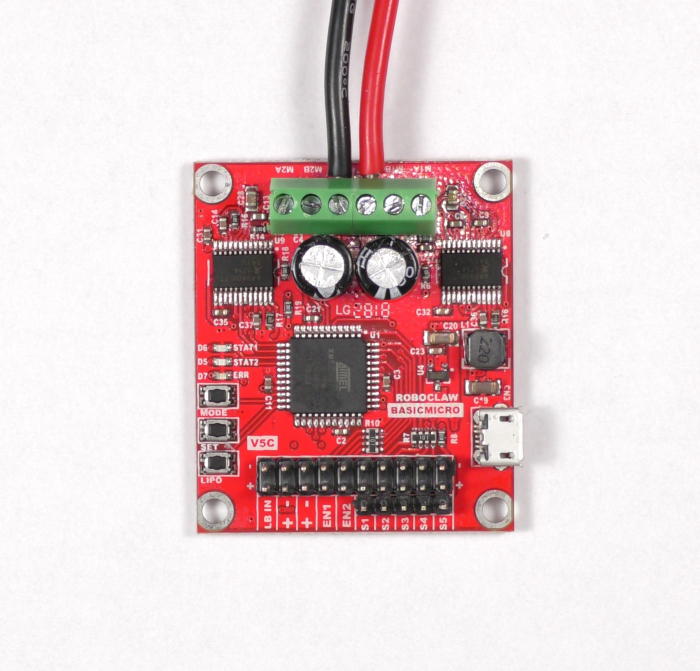
Figure 3: A battery properly wired to the board. -
Wire the first motor to the terminals labeled M1A and M1B. Loosen the screws on the terminals, place one motor wire in each terminal, and tighten the screws until the connections are snug. The order of the wires does not matter for the first motor.
-
Wire the second motor to the terminals labeled M2A and M2B. The order does matter for this motor. Note the color of the wire connected to the M1A terminal and connect the same colored wire of the second motor to the M2A terminal, then connect the remaining wire to the M2B terminal. If this motor is wired in the reverse order it will turn the wrong direction. Check that all motor connections are secure and will not come loose from the terminals.
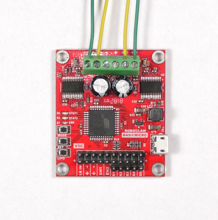
Figure 4: Two motors properly wired to the board.
Installing Motion Studio
-
Install Motion Studio by following Installing BasicMicro Motion Studio. Motion Studio installs from a single signed setup.exe, and no separate USB driver installation is required.
Turn on the RoboClaw’s power source, then connect the USB A to micro B cable between the RoboClaw and the computer.
Testing the Motors
-
Open Motion Studio. In the upper left-hand corner of the application is a box labeled “Attached Devices”. The RoboClaw should appear here. If it does not, check the USB connection and check that power has been properly applied to the RoboClaw. Select the device and click “Connect Selected Unit”. The Stat1 LED on the RoboClaw will begin flashing.
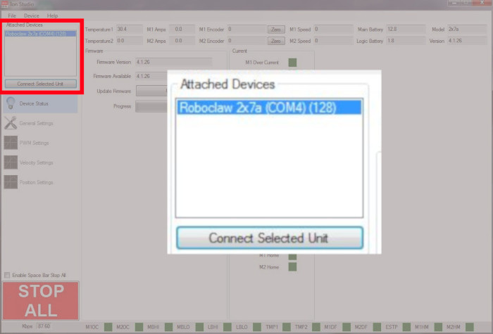
Figure 5: Where to connect a RoboClaw in Motion Studio. -
Click on “PWM Settings” in the left-hand pane. Find the box labeled “Control” and slide the sliders for Motor 1 and Motor 2. The motors should turn when operating the sliders, forwards when sliding up and backwards when sliding down. If a motor turns the wrong direction, its wiring needs to be reversed. Remove power from the RoboClaw before changing any wiring.
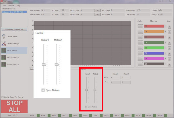
Figure 6: The sliders used to operate both motor channels. -
Disconnect the RoboClaw in Motion Studio by clicking “Disconnect Selected Unit”, then remove power from the RoboClaw before wiring the Arduino.
Wiring the Arduino
-
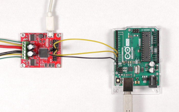
Locate the S1 and S2 pin headers on the RoboClaw. These are three-pin headers, and the pin on the outside edge of the board is the signal pin for each header. Using the jumper wires, connect pin 11 on the Arduino to the signal pin of S1 and pin 10 on the Arduino to the signal pin of S2.
-
Connect a ground pin on the Arduino to the ground pin of either the S1 or S2 header. The ground pin is the innermost pin of the header and is labeled on the board. Serial communication will not work without a common ground between the Arduino and the RoboClaw. If the Arduino is powered from USB or its own supply, no other power connection is needed between the two boards.
Once this ground jumper is in place, always remove power from the RoboClaw by disconnecting the positive battery lead, or both leads, never the negative lead alone. If only the negative lead is removed while the Arduino has its own power source, the RoboClaw can pull its ground return current through the ground jumper and the Arduino’s ground pin, which can damage the Arduino.
RoboClaw Arduino S1 signal pin (pin closest to the edge of the board) Pin 11 S2 signal pin Pin 10 S1 or S2 ground pin (pin closest to the inside of the board) Any ground pin 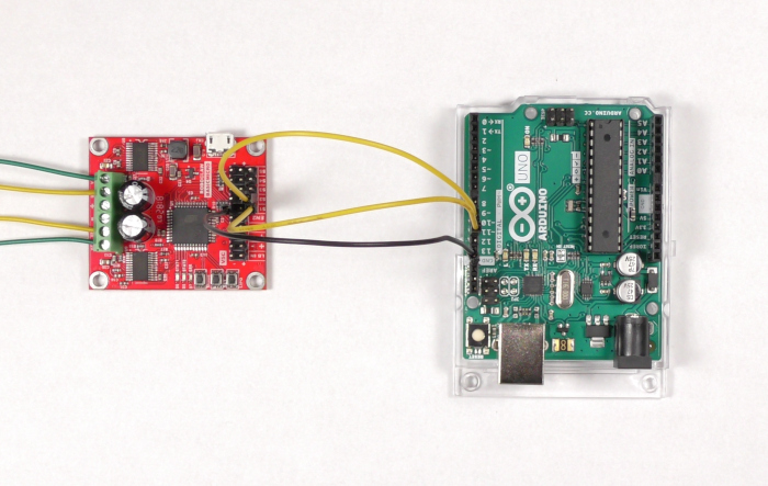
Figure 7: A RoboClaw and Arduino wired together.
Configuring Packet Serial Mode
-
Reconnect power to the RoboClaw, open Motion Studio, and connect the RoboClaw. Click on “General Settings” in the left-hand pane. Find the area labeled “Setup” and set the Control Mode to Packet Serial. Next, find the area labeled “Serial” and set the field labeled Packet Serial Address to 128. Finally, in the same area, set the field titled Baudrate to 38400. These values are used in the code running on the Arduino.
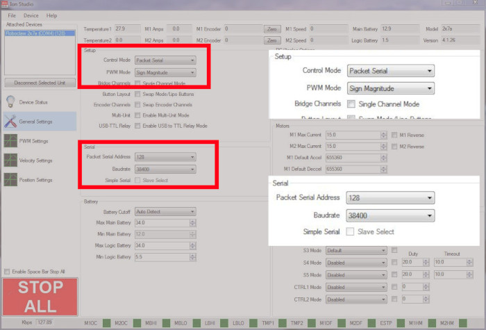
Figure 8: The location of the serial settings options. -
Save the settings to the board by clicking “Device” in the menu at the top of the application and then clicking “Write Settings”.
Installing the Basicmicro Arduino Library
-
In the Arduino IDE, go to Sketch > Include Library > Manage Libraries, search for “Basicmicro”, and click Install. For a full walkthrough of the library, see Using the RoboClaw Arduino Library.
Running the Example Sketch
-
Open a new sketch in the Arduino IDE and paste in the example code below. The sketch runs both motors forward, stops them, runs them in reverse, and stops them again in a loop.
SoftwareSerial is only available on AVR-based boards such as the Uno and Nano, and it requires
#include <SoftwareSerial.h>at the top of the sketch. For boards with additional hardware serial ports, see Using the RoboClaw Arduino Library for the hardware serial setup.#include <SoftwareSerial.h> #include <Basicmicro.h> SoftwareSerial controllerSerial(10, 11); // RX, TX Basicmicro roboclaw(&controllerSerial, 10000); #define ADDRESS 128 void setup() { roboclaw.begin(38400); } void loop() { // Run both motors forward at about 30% power roboclaw.DutyM1M2(ADDRESS, 10000, 10000); delay(2000); // Stop both motors roboclaw.DutyM1M2(ADDRESS, 0, 0); delay(1000); // Run both motors in reverse at about 30% power roboclaw.DutyM1M2(ADDRESS, -10000, -10000); delay(2000); // Stop both motors roboclaw.DutyM1M2(ADDRESS, 0, 0); delay(1000); } -
Connect the Arduino to the computer with its USB cable, select the board and port in the Arduino IDE, and click the Upload button to send the program to the Arduino.
-
The motors should now run forward, stop, reverse, and stop in a repeating cycle. If the system is not running properly, check that all connections are correct and secure. Common problems are reversed serial lines (RX and TX swapped) and reversed motor wiring. Remove power from the RoboClaw before changing any wiring.
How the Duty Commands Work
The example sketch uses the library’s duty cycle functions. These set each motor’s power directly as a percentage of the full battery voltage, with no PID tuning required. The address parameter identifies which RoboClaw receives the command, and the duty parameter is a signed 16-bit value: -32767 is full power in reverse, 0 is stopped, and 32767 is full power forward.
DutyM1(address, duty)
DutyM2(address, duty)
DutyM1M2(address, duty1, duty2)
DutyM1() and DutyM2() set the power of a single motor, and DutyM1M2() sets both motors in a single command. The value 10000 used in the sketch is roughly 30% of 32767, so the motors run at about 30% power.
roboclaw.DutyM1(ADDRESS, 16384);    // Motor 1 forward at about 50% power
roboclaw.DutyM2(ADDRESS, -16384);   // Motor 2 reverse at about 50% power
roboclaw.DutyM1M2(ADDRESS, 0, 0);   // Stop both motors
Next Steps
The Basicmicro Arduino library includes functions for speed control, position control, and reading data back from the RoboClaw. These application notes and examples cover them in detail:
- Using the RoboClaw Arduino Library
- Using Encoders with the Arduino Library
- Basicmicro Arduino library examples on GitHub


