Introduction
In another Application Note the Teensy was used with RoboClaw’s simple serial mode. This App Note covers using the Teensy to control RoboClaw in packet serial mode, which allows for more complex control as well as feedback from the motor controller.
Packet Serial Library
In packet serial mode a RoboClaw accepts multi-byte commands over a serial connection. A code library is used to simplify the process. This App Note uses the Arduino library which is available for free from BasicMicro’s GitHub profile.
Materials
(1) Teensy 3.2 microcontroller
(1) RoboClaw motor controller
(1) battery or power supply
(1) DC brushed motor with encoder
(1) breadboard
(3) female to male 0.1″ jumper wires
(1) micro USB cable
(1) computer with BasicMicro Motion Studio installed
(1) small screwdriver
(1) RoboClaw motor controller
(1) battery or power supply
(1) DC brushed motor with encoder
(1) breadboard
(3) female to male 0.1″ jumper wires
(1) micro USB cable
(1) computer with BasicMicro Motion Studio installed
(1) small screwdriver
Let’s Get Started
1. The Teensy’s header pins must be soldered on before starting this tutorial. Header pins are supplied with each brand new Teensy and should be soldered on with the pins facing down so that the Teensy can be inserted in to a breadboard.
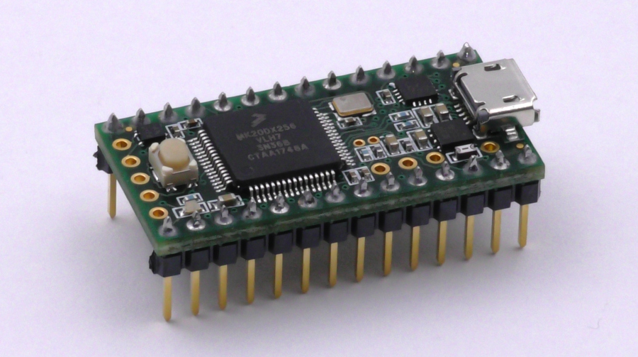
Figure 2: A Teensy with header pins soldered on.
2. Begin by following these instructions to start setting up the Teensy micrcontroller. If a Teensy has already been setup steps 2 and 3 can be skipped.
3. Next, the Teensy’s Arduino compatibility software must be installed and configures. Follow these instructions to install the software.
4. Add the RoboClaw library to the Arduino by the following the section labeled “Adding the RoboClaw library to the Arduino IDE” in this App Note.
5. Follow this tutorial through step 10 to wire the motor and power connections to the RoboClaw.
6. Wire the encoder to the RoboClaw. Use this Application Note as a guide.
7. Turn on the RoboClaw by connecting power to it.
8. Connect the RoboClaw to a computer using a mini USB cable.
9. Open Motion Studio and connect the RoboClaw by clicking “Connect Selected Unit”. Next click on “General Settings” on the left-hand side of the application. Locate the pane labeled “Setup” and set the control mode to “Packet Serial”. Now located the pane labeled “Serial” and set the baudrate to “38400” and the “Address” to 128. To complete the RoboClaw’s configuration click on “Device” in the menu at the top of the application and then click on “Write Settings” in the menu that appears.
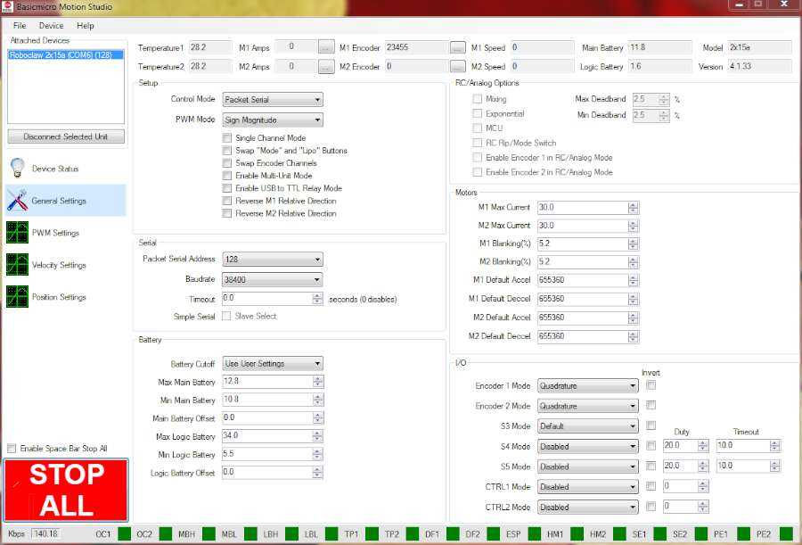
Figure 3: Control mode and serial settings for packet serial mode.
10. Disconnect the USB cable from the RoboClaw and then disconnect power from the RoboClaw.
11. Place the Teensy in the breadboard making sure it’s fully seated, then wire the RoboClaw and Teensy together according to the table below using a pair of female to male jumper cables.
| Function | Teensy | Roboclaw |
| Transmit | Pin 1 (see Teensy documentation for pinout diagram) | S1 signal pin (S1 header pin closest to the outside of the board) |
| Receive | Pin 0 (see Teensy documentation for pinout diagram) | S2 signal pin (S2 header pin closest to the outside of the board) |
| Ground | Ground pin | S1 ground pin (S1 header pin closest to the inside of the board) |
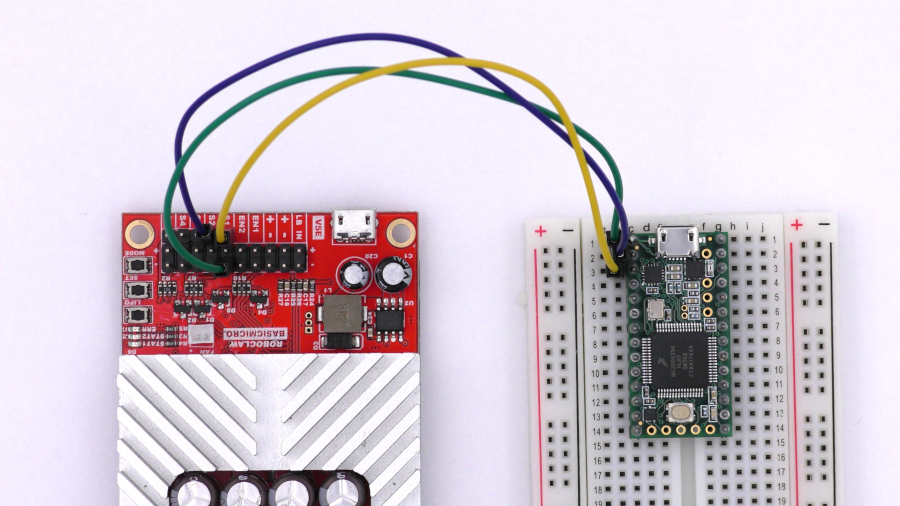
Figure 4: The Teensy and RoboClaw wired together.
12. Turn the RoboClaw back on by reconnecting power to it.
13. Connect the Teensy to the computer with a micro USB cable.
14. Download the code for this application note from Github. The code can be directly downloaded from here or from the commandline if Git is installed. The command below can be used to pull the code from GitHub via the commandline.
git clone https://github.com/basicmicro/teensy_packet_serial.git
15. Open the Arduino IDE and check that the Teensy Board and the proper com port is selected from the “Tools” menu.
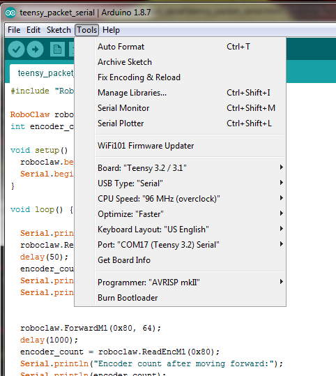
Figure 5: The tools menu of the Arduino IDE showing Teensy settings.
16. From the IDE open the code downloaded in the previous step. Click the checkmark labeled “Verify” to compile the project. The Teensy loader will open and prompt to press the button on the Teensy board. Finally, click on the upload button to send the compiled code to the Teensy board.
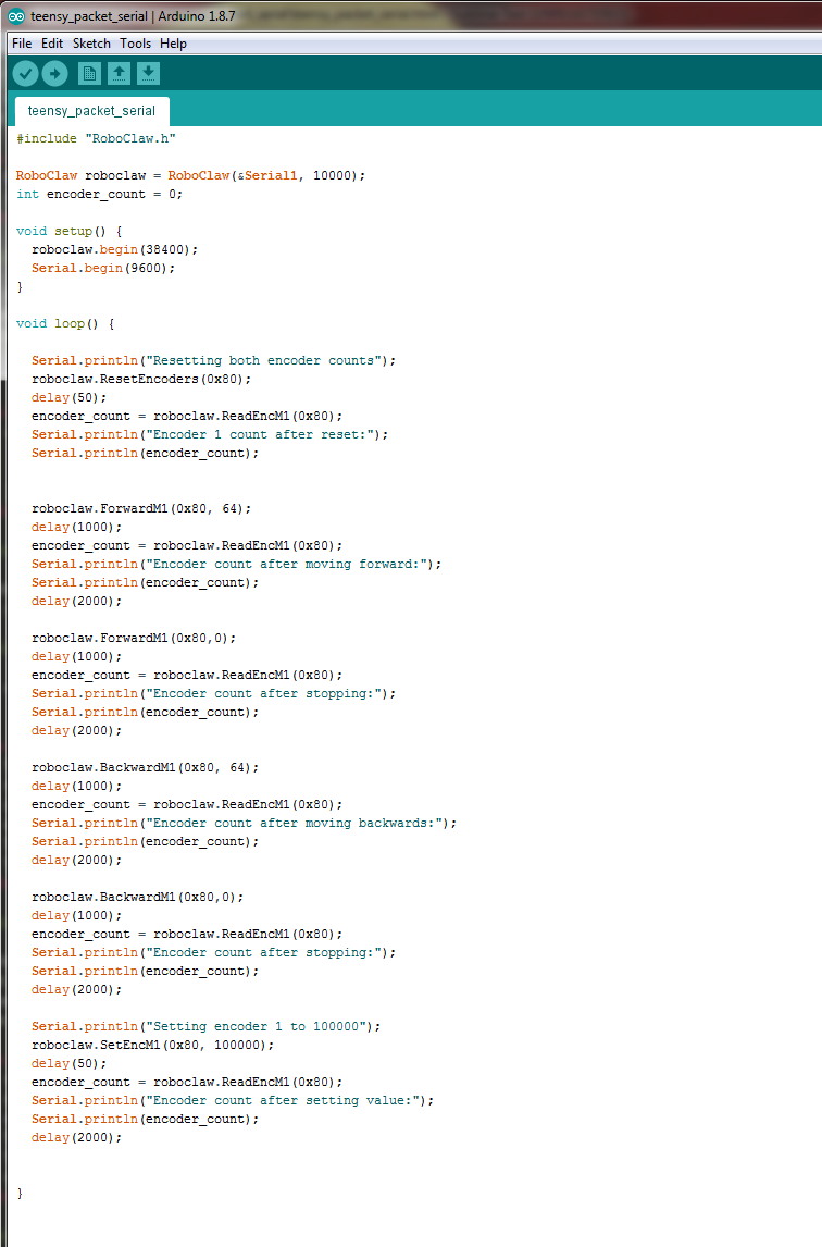
Figure 6: The example code opened in the Arduino IDE.
17. If everything is working correctly the motor should turn in the forward direction at half speed for two seconds, stop for two seconds and then turn in the reverse direction for two seconds before pausing and starting again. The text output of the program can be seen by opening the serial monitor of the Arduino IDE. The program will display status messages and encoder counts in the serial monitor. Be sure that the proper port has been set for the Teensy or the serial monitor functionality will not work.
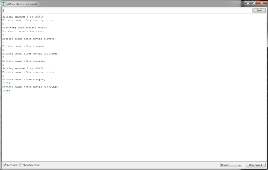
Figure 6: The example code opened in the Arduino IDE.
Code Walkthrough
#include “RoboClaw.h”
The first line of the program brings in the RoboClaw Arduino library. The library is used for creating the RoboClaw object and contains all of the functions that will be called on the object to control the motor controller.
RoboClaw roboclaw = RoboClaw(&Serial1, 10000);
int encoder_count = 0;
int encoder_count = 0;
The first line of the above code creates the RoboClaw object which is the first step in the software side of using the packet serial functionality of the RoboClaw. Two parameters are passed to the constructor: the address of the first harwdare serial port of the Teensy and a timeout value expressed in millseconds.
The second line creates a variable to hold the encoder counts that will be read from the RoboClaw later in the program. The variable is initialized to zero.
void setup() {
roboclaw.begin(38400);
Serial.begin(9600);
}
roboclaw.begin(38400);
Serial.begin(9600);
}
In the setup function the serial port for the RoboClaw object by calling the “begin()” function and passing it the baudrate that was set in Motion Studio. Next the serial port associated the USB port of the Teensy is started so that output from the program can be seen in the Arduino serial monitor.
All of the following code is contained in the “loop()” function:
Serial.println(“Resetting both encoder counts”);
roboclaw.ResetEncoders(0x80);
delay(50);
encoder_count = roboclaw.ReadEncM1(0x80);
Serial.println(“Encoder 1 count after reset:”);
Serial.println(encoder_count);
roboclaw.ResetEncoders(0x80);
delay(50);
encoder_count = roboclaw.ReadEncM1(0x80);
Serial.println(“Encoder 1 count after reset:”);
Serial.println(encoder_count);
In this block of code the encoders are reset by calling “ResetEncoders(0x80)” on the RoboClaw object. The 0x80 parameter is the address of the motor controller that was set in Motion Studio. In the previous instructions the address was set to 128, 0x80 is the hexidecimal representation of 128. The encoder count for motor channel 1 is read by calling “ReadEncM1(0x80)” and the result stored in the variable “encoder_count” that was created earlier. The encoder count value is then printed to the serial monitor.
roboclaw.ForwardM1(0x80, 64);
delay(1000);
encoder_count = roboclaw.ReadEncM1(0x80);
Serial.println(“Encoder count after moving forward:”);
Serial.println(encoder_count);
delay(2000);
delay(1000);
encoder_count = roboclaw.ReadEncM1(0x80);
Serial.println(“Encoder count after moving forward:”);
Serial.println(encoder_count);
delay(2000);
In this block of code begins with a call to “ForwardM1(0x80,64)”. This instructs the RoboClaw to drive motor 1 in the forwards direction at half speed. 0x80 is the address of the RoboClaw, as seen in previous calls, and the 64 parameter set the speed of the motor to half speed. Once again the encoder count is read and printed to the serial monitor.
roboclaw.ForwardM1(0x80,0);
delay(1000);
encoder_count = roboclaw.ReadEncM1(0x80);
Serial.println(“Encoder count after stopping:”);
Serial.println(encoder_count);
delay(2000);
delay(1000);
encoder_count = roboclaw.ReadEncM1(0x80);
Serial.println(“Encoder count after stopping:”);
Serial.println(encoder_count);
delay(2000);
This block of code is identical to the last except a speed of zero is passed to the “ForwardM1()” function, which stops the motor.
roboclaw.BackwardM1(0x80, 64);
delay(1000);
encoder_count = roboclaw.ReadEncM1(0x80);
Serial.println(“Encoder count after moving backwards:”);
Serial.println(encoder_count);
delay(2000);
delay(1000);
encoder_count = roboclaw.ReadEncM1(0x80);
Serial.println(“Encoder count after moving backwards:”);
Serial.println(encoder_count);
delay(2000);
In this block of code the call to drive the motor forward is replaced by a call to “BackwardM1(0x80, 64)” which instructs the RoboClaw to drive motor 1 in the backwards direction at half speed. Everything else is the same as similar blocks.
roboclaw.BackwardM1(0x80,0);
delay(1000);
encoder_count = roboclaw.ReadEncM1(0x80);
Serial.println(“Encoder count after stopping:”);
Serial.println(encoder_count);
delay(2000);
delay(1000);
encoder_count = roboclaw.ReadEncM1(0x80);
Serial.println(“Encoder count after stopping:”);
Serial.println(encoder_count);
delay(2000);
As with stopping the motor by passing a zero to “ForwardM1()” the first line of this block stops the motor by passing a zero to “BackwardM1()”. Everything else is the same as similar blocks.
Serial.println(“Setting encoder 1 to 100000”);
roboclaw.SetEncM1(0x80, 100000);
delay(50);
encoder_count = roboclaw.ReadEncM1(0x80);
Serial.println(“Encoder count after setting value:”);
Serial.println(encoder_count);
delay(2000);
roboclaw.SetEncM1(0x80, 100000);
delay(50);
encoder_count = roboclaw.ReadEncM1(0x80);
Serial.println(“Encoder count after setting value:”);
Serial.println(encoder_count);
delay(2000);
In the final block of code a new function is called: “SetEncM1()”. This function set the internal encoder value for motor channel 1 on the RoboClaw to the value of the second parameter to the function. In this case the value is set to 100,000. To prove that it was set propely the encoder value is read after setting it and then it’s printer to the serial monitor.