About Limit and Home Switches
RoboClaw motor controllers support both limit and home switch functionality that can be configured in a variety of ways. This Application Note covers the wiring and configuration of both. Limit switches are often used in linear systems to prevent movement beyond the mechanical limits of the system. A home switch is usually used to create a known starting point for a moving component. A known starting, or zero point, is useful when using quadrate encoders to track precise movements.
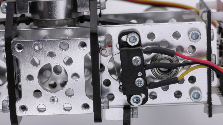
Figure 1: An image of a limit switch installed.
Wiring
Limit and home switches are wired to the S4 and S5 pin headers on RoboClaw. Normally them operate by shorting the signal pin of the header to ground. To make this work properly a normally open switch should be used. However if the switches in use are normally closed switched the invert option can be set in Motion Studio to make them work properly. Also, if the wiring between the switch and the motor controller is longer than a few feet the use of an active pullup is recommended. Servo connectors or other 0.1″ female headers should be used to connect the switch’s wiring to the RoboClaw as the pin header on the motor controller is a 3 pin header with 0.1″ pin spacing.
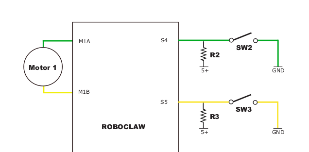
Figure 2: Wiring diagram for limit and home switches. Note the switches in this diagram are normally open (NO) switches.
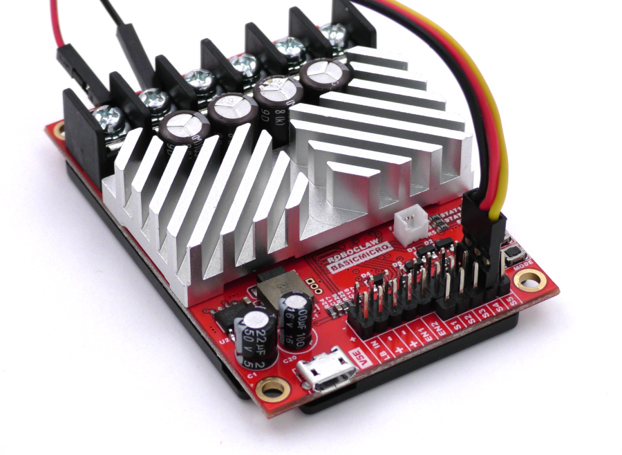
Figure 3: A limit switch for motor channel 1 wired to the S4 header.
Configuration
The limit and home switch functionality is configured in Motion Studio. Open Motion Studio, connect the motor controller in use and then click on “General Settings” on the left-hand side of the application. The pane labeled “I/O” contains two dropdowns labeled “S4 Mode” and “S5 Mode”. These two options are where limit and home switch settings are set. Header S4 corresponds to motor channel 1 and header S5 corresponds to motor channel 2. To set an option select it from the dropdown and save the settings to the board by selecting “Device” in the menu at the top of the application and clicking on “Write Settings”. Below is a list and description of all the options available for both headers.
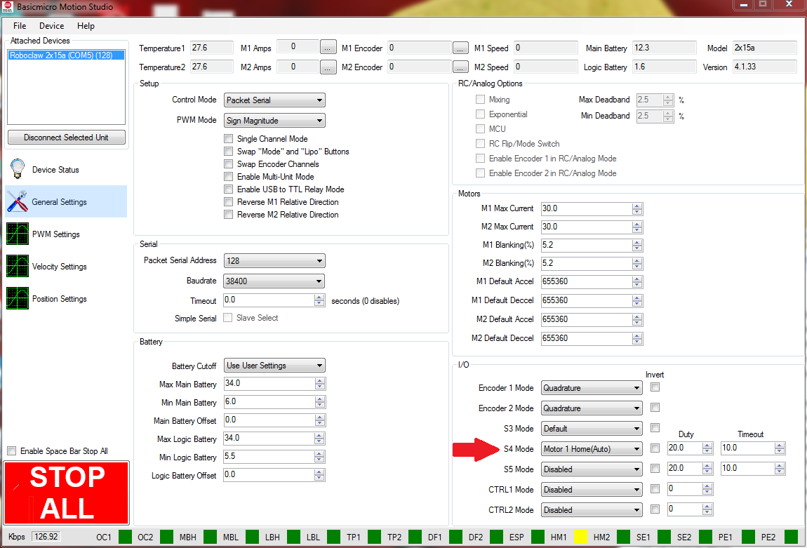
Figure 4: Motion Studio configuration for limit and home switches.
Home (Auto)
This option instructs the RoboClaw to automatically drive the given motor channel to the position where the home switch is triggered.
Home (User)
This options allows the user to drive the given motor channel to the home position manually. Once triggered the motor channel stops driving the motors.
Home (Auto)/Limit(Fwd)
This options enables automatic homing and allow another switch to act as a limit switch when the given motor is moving in the forward direction.
Home (User)/Limit(Fwd)
This option enables manual homing and allows another switch to act as a limit switch when the given motor is moving in the forward direction.
Limit (Fwd)
This option stops the given motor when the limit switch is triggered while the motor is moving in the forward direction.
Limit (Rev)
This option stops the given motor when the limit switch is triggered while the motor is moving in the reverse direction.
Limit (Both)
This option stops the given motor when the limit switch is triggered while the motor is moving in either direction.