Introduction
The esp8266 is an incredibly inexpensive and powerful microcontroller and wifi development platform has gained a large following in the hobbyist electronics market. There are a variety of languages for programming the esp8266 however the Arduino platform is one of the most popular. Since BasicMicro supplies an Arduino library for controlling a RoboClaw an esp8266 can be used to control the motor controller wirelessly. This Application Notes looks at configuring a simple demonstration of the ability to control a RoboClaw from any wireless device with a web browser.
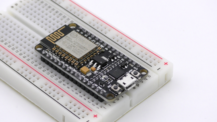
Figure 1: A late prototype of the Super Gamer case.
Materials
(1) RoboClaw motor controller
(1) DC brushed motor
(1) power supply for RoboClaw
(1) NodeMCU esp8266 1.0 board
(1) breadboard
(3) 0.1″ female to male jumper cables
(1) micro USB cable
(1) computer with Motion Studio and Arduino IDE installed
(1) small screwdriver
(1) DC brushed motor
(1) power supply for RoboClaw
(1) NodeMCU esp8266 1.0 board
(1) breadboard
(3) 0.1″ female to male jumper cables
(1) micro USB cable
(1) computer with Motion Studio and Arduino IDE installed
(1) small screwdriver
Let’s Get Started
1. Follow this Application Note to step 10 to wire the RoboClaw’s power and motor connections.
2. Turn the RoboClaw on by connecting power to it.
3. Connect the RoboClaw to a computer with a micro USB cable. Open Motion Studio and connect the RoboClaw by clicking “Connect Selected Unit”. Click on “General Settings” on the left-hand side of the application. Locate the pane labeled “Setup” and set the dropdown label “Control Mode” to Packet Serial. Next locate the pane labeled “Serial”. Set the “Packet Serial Address” to 128 and set the drop down labeled “Baudrate” to 38400.
Save the settings to the board by opening the menu option labeled “Device” at the top of the application and clicking “Write Settings”. Finally click “Disconnect Selected Unit” to disconnect the RoboClaw.
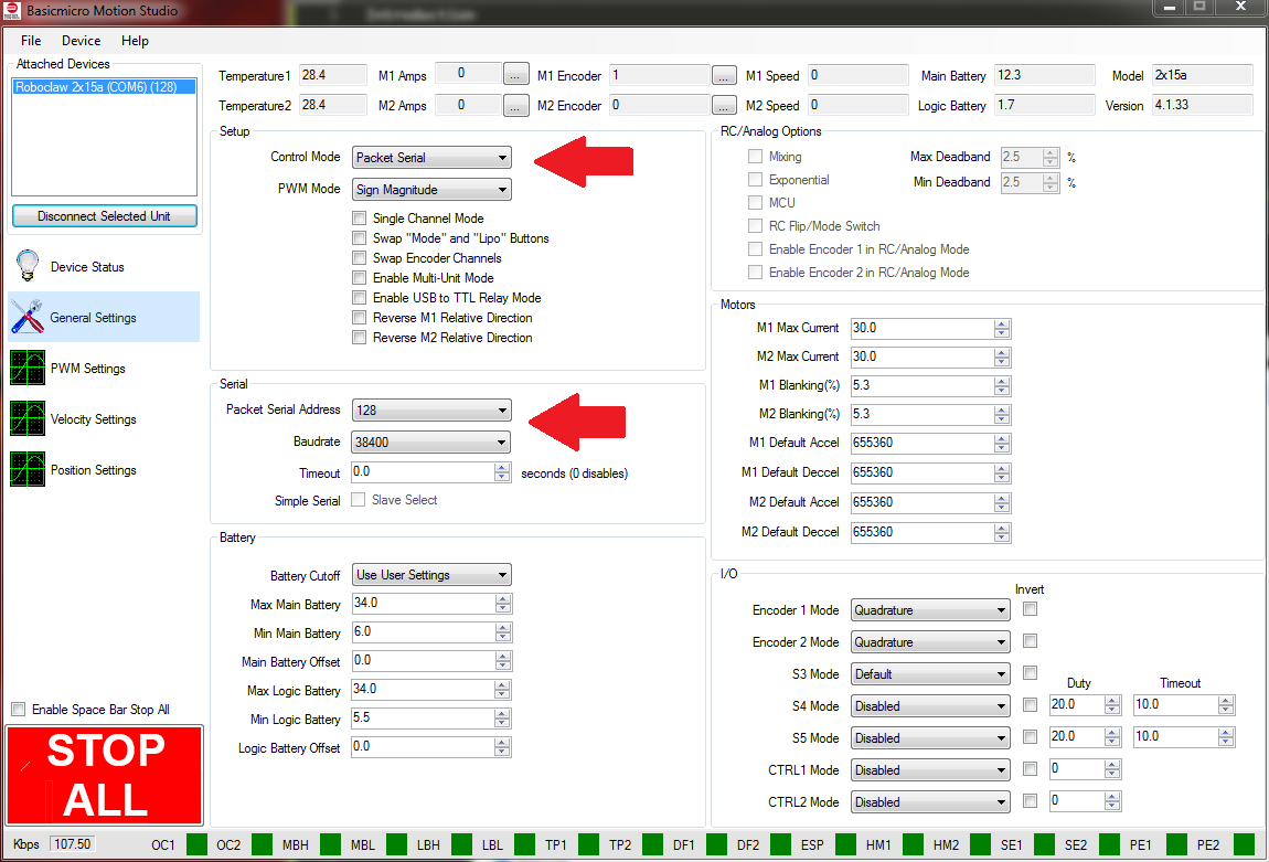
Figure 2: The mode and serial setting in Motion Studio.
4. Turn the RoboClaw off by disconnecting it’s power supply.
5. Place the esp8266 board in the breadboard leaving room on either side for connections.
6. Wire the RoboClaw and the esp8266 board together with jumper wires according to the table below. There is also a photo below of the two boards wired together.
| Function | esp8266 | RoboClaw |
| Ground | Ground pin | S1 ground pin |
| Transmit | GPIO15 | S1 signal pin |
| Receive | GPIO 13 | S2 signal pin |
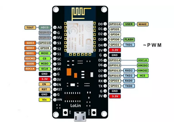
Figure 3: The pinout of the NodeMCU esp8266 board.
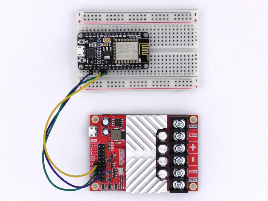
Figure 4: The RoboClaw and esp8266 wired together.
7. Install the esp8266 board software and libraries by following this documentation.
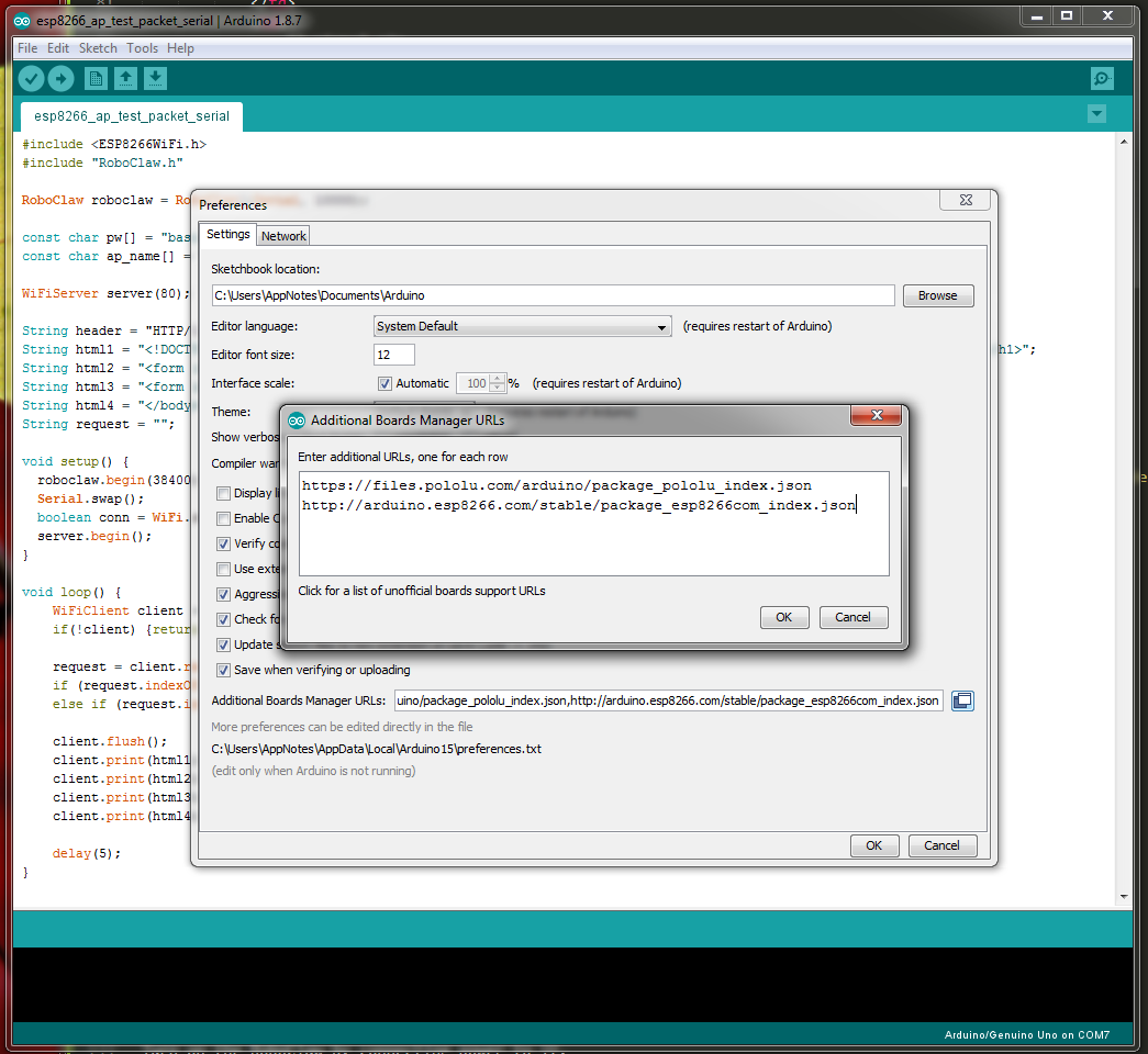
Figure 5: The Arduino IDE board manager.
8. Follow the section labeled “Adding the RoboClaw library to the Arduino IDE” in this app note to install the RoboClaw library.
9. Connect the esp8266 board to a computer with a micro USB cable. Using the computer’s system tools determine what serial port the board is on. In the Arduino IDE open the “Tools” menu and set the esp8266 board in use and the port. The board used in this app note is the NodeMCU 1.0.
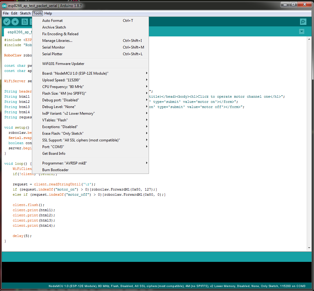
Figure 6: The board settings for the NodeMCU board in the Arduino IDE. Note that the port number will vary from system to system.
10. The example code for this app note can be downloaded from GitHub or cloned from the commandline if Git is installed on the computer being used.
To clone the code repository enter the following on the commandline:
git clone https://github.com/basicmicro/roboclaw_esp8266_basic.git
11. Turn on the RoboClaw by connecting power to it.
12. In the Arduino IDE open the example code for this app note. Click on the right-hand arrow button to compile the code and upload it to the esp8266.
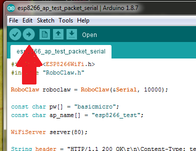
Figure 7: Location in the Arduino IDE to compile and upload to the board.
13. Using a computer, tablet or phone connect to the access point named “esp8266_test” and enter the password “basicmicro” (without quotes). Open a browser and navigate to “192.168.4.1”. A webpage should be diplayed with two buttons, one to turn the motor on and another to turn the motor off. If nothing happens after pressing the buttons make sure that the serial lines are not wired up backwards and that there is a ground connection between the esp8266 and the RoboClaw. Finally make sure that the mode and serial settings in Motion Studio match those in the example code.
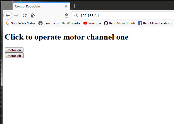
Figure 8: The webpage for controlling a RoboClaw.
Code Walkthrough
The RoboClaw specific and important lines of code in the example are detailed below:
#include <ESP8266WiFi.h>
#include “RoboClaw.h”
#include “RoboClaw.h”
Here there are two include statements. The first includes the esp8266 wifi library and the second includes the RoboClaw library.
RoboClaw roboclaw = RoboClaw(&Serial, 10000);
This line of code creates the RoboClaw object. The address of hardware serial object is passed to the constructor as well as a timeout value of 10,000 milliseconds (10 seconds).
void setup() {
roboclaw.begin(38400);
Serial.swap();
boolean conn = WiFi.softAP(ap_name, pw);
server.begin();
}
roboclaw.begin(38400);
Serial.swap();
boolean conn = WiFi.softAP(ap_name, pw);
server.begin();
}
In the setup function several things are initialized and started. First the communication with the RoboClaw is started with a baudrate of 38400 bps. Second, the serial pins are swapped so that GPIO13 and GPIO15 are used instead of the standard pins. Next, the access point is started with the password and ssid set earlier. Finally, the webserver is started.
request = client.readStringUntil(‘\r’);
if (request.indexOf(“motor_on”) > 0){roboclaw.ForwardM1(0x80, 127);}
else if (request.indexOf(“motor_off”) > 0){roboclaw.ForwardM1(0x80, 0);}
if (request.indexOf(“motor_on”) > 0){roboclaw.ForwardM1(0x80, 127);}
else if (request.indexOf(“motor_off”) > 0){roboclaw.ForwardM1(0x80, 0);}
In this block of code the requests sent to the server are read and the path searched for references to either “motor_on” or “motor_off”. If either of those is detected in the request a call is made on the RoboClaw object to start or stop motor channel 1.