
A quadrature encoder outputs two square wave signals, called A and B, offset by 90 degrees. That offset lets a motor controller determine direction from which signal leads, count pulses to track position, and measure the pulse rate to calculate speed. It is the standard feedback device for closed-loop motor control.
What Is a Quadrature Encoder?
A quadrature encoder is an incremental encoder with two output channels. One common construction is a disc with two tracks of evenly spaced markings, offset from each other by a quarter of a marking width; as the shaft rotates, each track passes a sensor that produces one pulse per marking. Other designs sense a single repeating pattern at two offset positions. Either way, the two output streams are 90 degrees out of phase, one quarter of a full cycle. That quarter-cycle relationship is where the name quadrature comes from. For how incremental encoders compare with absolute encoders, see Encoders Explained.
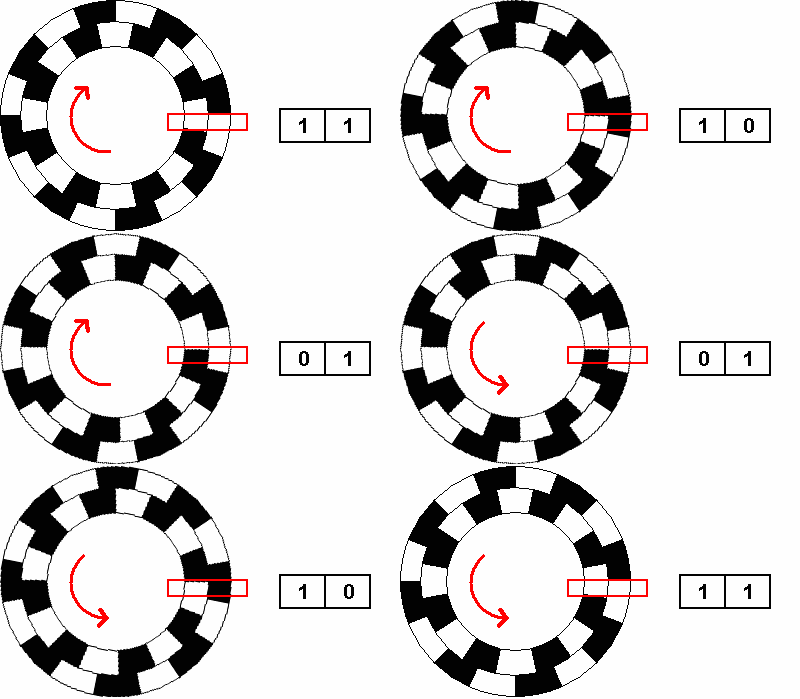
The sensing technology varies. Optical encoders shine light through a slotted disc, magnetic encoders read a magnetized ring, and capacitive designs measure a patterned rotor. All of them produce the same two-channel quadrature output, so the decoding described below applies regardless of how the pulses are generated. RoboClaw and MCP motor controllers decode this output in hardware.
How Do the A and B Signals Work?
Watch the two channels together and the shaft’s motion becomes a repeating sequence of states. Each full cycle of the A signal passes through four distinct combinations of A and B:
| Step | Channel A | Channel B |
|---|---|---|
| 1 | Low | Low |
| 2 | High | Low |
| 3 | High | High |
| 4 | Low | High |
Rotating in one direction, the states advance 1, 2, 3, 4 and repeat. Rotating in the other direction, the same states appear in reverse order: 4, 3, 2, 1. In a valid quadrature sequence, only one channel changes state at each transition. A reading where both channels appear to change at once indicates a missed transition, usually caused by electrical noise or a pulse rate faster than the decoder can follow.
How Does a Controller Decode Direction?
Direction comes from which channel leads. If channel A rises before channel B, the shaft is turning one way; if B rises before A, it is turning the other way. A decoder implements this by watching for an edge on either channel and checking the state of the opposite channel at that moment. Using one common counting convention, if A rises while B is low, the count goes up; if A rises while B is high, the count goes down.
This is why a quadrature encoder needs two channels. A single pulse stream can measure speed, but it carries no direction information: the pulses look identical whether the shaft turns forward or backward. The 90-degree offset is what adds direction, turning a simple pulse count into bidirectional position feedback.
What Is the Difference Between Pulses, Counts, and CPR?
Encoder resolution terminology is genuinely inconsistent between manufacturers, and it is the most common source of math errors in motor control setups.
Pulses per revolution (PPR) is the number of full cycles one channel produces in one shaft revolution, set by the number of markings on the disc. Counts are what the decoder actually tallies. Each cycle contains four signal edges, two on each channel, so a decoder can register one, two, or four counts per cycle depending on how many edges it watches. Full 4x quadrature decoding counts every rising and falling edge of both A and B, producing four counts for each complete cycle. CPR is the ambiguous one: some datasheets use it to mean cycles per revolution, identical to PPR, while others mean counts per revolution after 4x quadrature decoding. The two readings differ by a factor of four, so check which convention a datasheet follows before doing the math.
Gear reduction multiplies resolution at the output shaft. An encoder on the motor shaft turns once per motor revolution, so counts at the output shaft scale with the gear ratio:
Encoder resolution: 16 pulses per revolution (one channel)
Decoding:           x4 (every edge of A and B)
Gear ratio:         50:1

Counts per motor revolution  = 16 x 4 = 64
Counts per output revolution = 64 x 50 = 3200
When a datasheet leaves room for doubt, measure instead of calculating. Rotate the output shaft exactly one revolution by hand and read how much the encoder count changed. RoboClaw reports the running count in Motion Studio and stores it as a full 32-bit value, so the measured number is definitive for the exact motor, encoder, and decoder in use.
How Do You Wire a Quadrature Encoder?
A basic single-ended quadrature encoder typically takes four connections: power, ground, and the two signal channels. RoboClaw’s main header provides +5V and ground alongside the A and B inputs for each motor channel. Pololu Encoder Wiring walks through the connection on a typical hobby gearmotor.
A few signal details matter for reliability. Encoders with open-collector or open-drain outputs need pull-up resistors on the signal lines, and a bypass capacitor across the encoder’s power pins helps filter supply noise. RoboClaw accepts quadrature inputs directly without built-in signal conditioning, a design choice that keeps the maximum count speed high, so weak or noisy encoder signals must be conditioned externally. In electrically noisy environments, differential encoders are strongly recommended for their noise immunity. If counts are erratic or position drifts unexpectedly, inspect the A and B signals with an oscilloscope.
Verify encoder direction before enabling closed-loop control. Drive the motor forward at low power and confirm the encoder count increases. If the count decreases, swap either the motor wires or the encoder’s A and B wires. A reversed encoder turns the feedback loop into a runaway: the controller sees the error growing and applies more power in the wrong direction.
Quadrature encoders track position relative to a starting reference. If the machine’s absolute position matters, home the mechanism after power-up, then set or reset the encoder count at that known position.
Quadrature decoding is built into every RoboClaw motor controller, from 7A to 300A, on both channels of the dual models.
Next Steps
With the signals understood, Pololu Encoder Wiring covers the physical hookup step by step. Using Encoders with the Arduino Library and Using Encoders with the Python Library show how to read counts and speeds in code, and Auto Tuning with Motion Studio turns a wired encoder into working velocity and position control. For how encoders fit into complete machines, see Encoders in Robotics.


