
RoboClaw hardware revisions V5 and under can be configured without a computer using the onboard MODE, SET, and LIPO buttons. These buttons set the control mode, mode options, and battery cutoff settings, with the STAT2 LED blinking to indicate the current selection. Current RoboClaw hardware is configured in Motion Studio instead.
Current RoboClaw hardware no longer has buttons and must be configured from Motion Studio. This guide applies to hardware revisions V5 and under. For configuring a RoboClaw with Motion Studio, see the Solo Quick Start Guide and the Dual Channel RoboClaw Quick Start Guide.
There may be times when you do not have a computer available to configure your RoboClaw. On hardware revisions V5 and under, the onboard buttons let you set the control mode and options without having to use Motion Studio. This guide covers several common configurations using only the onboard buttons.
Using the Buttons
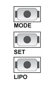
Each setup uses the buttons labeled MODE, SET, and LIPO. These are located on the side of the board opposite the USB connector. The buttons are used to enter the programming mode, select modes and options, and save the settings. While programming the mode and settings, the STAT2 LED will blink to indicate the mode or option selected.
Differential Drive RC Setup
A differential drive setup is best illustrated with a tank style robot. Forwards and backwards motion is done with both motors turning the same way, and turning is accomplished by slowing the motor on the side associated with the turning direction; for faster turns the appropriate motor is reversed. The steps below configure the RoboClaw to operate in this mode while being controlled by an RC radio system.
-
Press the MODE button and release it. The STAT2 LED will blink a number of times to indicate the currently saved mode. Press SET until the STAT2 LED blinks twice. This puts the RoboClaw into RC mode with mixing. The mixing setting is what allows the RoboClaw to operate both motors in a tank robot style. Press and release the LIPO button to save the setting.
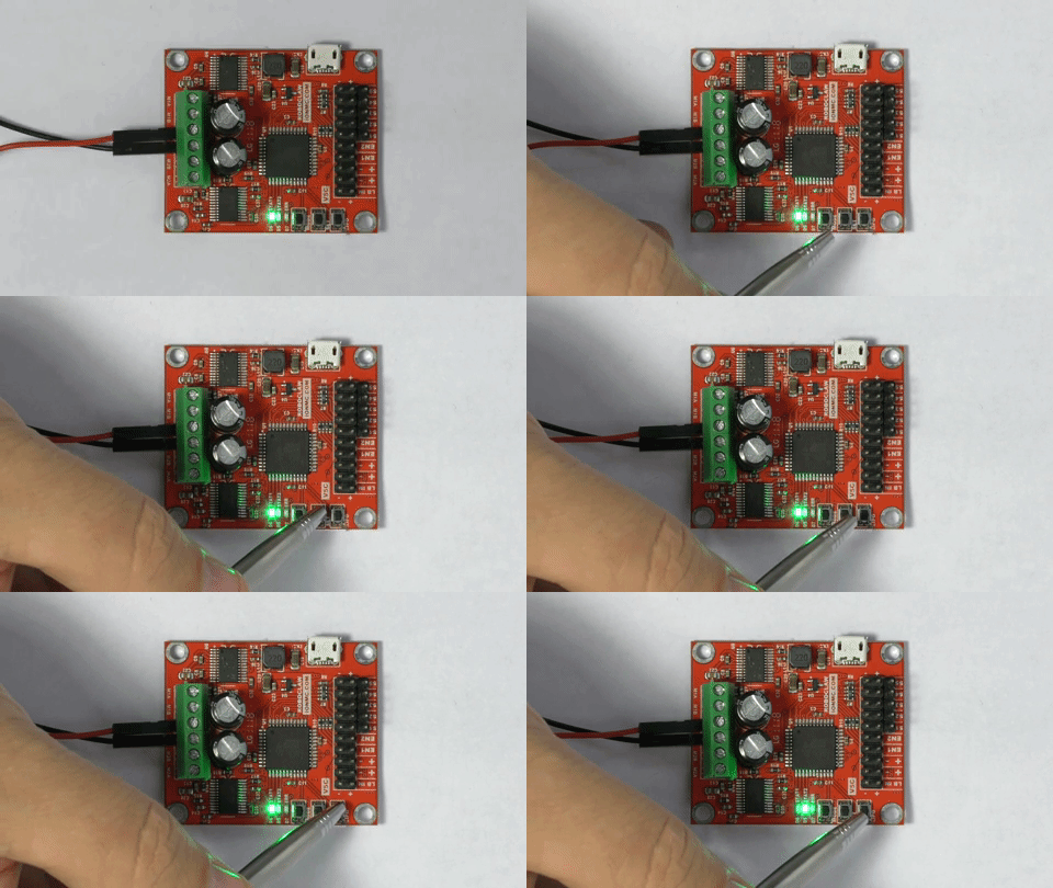
Figure 2: Setting RC mode with mixing. -
Now set the options for the RC mode that was set in the last step. Press and release the SET button. Once again the STAT2 LED will blink to indicate the current option set selected. We’ll be setting the RC flip switch option with exponential enabled. Press the SET button until the STAT2 LED flashes 6 times. With these options enabled you will be able to use an additional RC channel to change the control scheme if your robot is flipped over. This means that if your robot is flipped you will not need to mentally reverse the controls in your head; with the flip of a switch you can restore the control scheme you are used to. The exponential option makes your robot easier to control by softening the control stick response near the center of the stick’s travel, making the robot less sensitive to small control inputs.
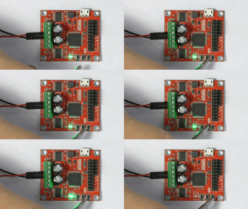
Figure 3: Setting RC flip switch mode with exponential enabled.
Arduino Control Setup
When using an Arduino to control a RoboClaw you have several methods available for control. In this example the RoboClaw will be configured to operate in packet serial mode.
-
Press the MODE button and release it. The STAT2 LED will blink a number of times to indicate the currently saved mode. Press SET until the STAT2 LED blinks 7 times. This puts the RoboClaw into packet serial mode with an address of 0x80. This allows the RoboClaw and the Arduino to communicate over a serial connection. Press and release the LIPO button to save the mode setting.
-
The baud rate can be set as an option. If you do not set this option the baud rate will be 38400bps. This is a sane value for the Arduino, however the Arduino can utilize a baud rate up to 115200bps. To begin, press and release the SET button. Once again the STAT2 LED will blink to indicate the current option set selected. Press the SET button until the LED indicates you have reached the setting of your choice.
Option Baud Rate 1 2400bps 2 9600bps 3 19200bps 4 38400bps 5 57600bps 6 115200bps 7 230400bps 8 460800bps
Differential Drive Analog Setup
When used in analog mode the RoboClaw can use potentiometers or controllers that output an analog signal, like joysticks, to control the RoboClaw. With a differential drive system two motors are used to control forwards and backwards motion as well as turning. Tank style robots are an example of robots that use this configuration.
-
Press the MODE button and release it. The STAT2 LED will blink a number of times to indicate the currently saved mode. Press SET until the STAT2 LED blinks four times. This puts the RoboClaw into analog mode with mixing. The mixing setting is what allows the RoboClaw to operate both motors in a tank robot manner. Press and release the LIPO button to save the mode setting.
-
Now set the options for the analog mode that was set in the last step. Press and release the SET button. Once again the STAT2 LED will blink to indicate the current option set selected. We’ll be setting the TTL flip switch option with exponential enabled. Press the SET button until the STAT2 LED flashes 2 times. With these options enabled you will be able to use an external switch, like a mercury switch, to change the control scheme if your robot is flipped over. The exponential option makes your robot easier to control.
Battery Mode Configuration
Regardless of the mode the RoboClaw is put in, you will need to configure your battery settings to protect the batteries from over and under voltage conditions. If you are using LiPO batteries we recommend that you use the cell count setting.
-
Press and release the LIPO button. As before, the STAT2 LED will flash to indicate what option is currently set. Consult the table below and press the SET button until the LED indicates you have reached the setting you’re looking for. Then press and release the LIPO button to save your battery setting.
Option Setting Description 1 Disabled 6VDC cutoff when disabled 2 Auto Detect Battery must not be under or overcharged 3 3 Cell 9VDC is the cutoff voltage 4 4 Cell 12VDC is the cutoff voltage 5 5 Cell 15VDC is the cutoff voltage 6 6 Cell 18VDC is the cutoff voltage 7 7 Cell 21VDC is the cutoff voltage 8 8 Cell 24VDC is the cutoff voltage
Next Steps
The settings configured with the buttons will remain in memory as long as they were saved with the LIPO button. See the manual for the full range of settings and options that can be configured through the onboard buttons, and these guides for related configuration: