
Motion Studio can automatically tune the PID values that RoboClaw uses for velocity and position control. This guide walks through auto tuning both control modes step by step: verifying motor and encoder operation, measuring the maximum QPPS, running Auto Tune, testing the results, and fine tuning the values by hand when needed.
Tuning a PID controller can seem more like an art than a science at times. Thankfully, Motion Studio has the ability to automatically tune the three PID controller coefficients. This guide covers how to use that functionality and how to do any additional fine tuning necessary.
The P, I, and D terms in PID stand for proportional, integral, and derivative. Each term compensates for error between a setpoint and the actual value measured: the proportional term corrects for the current error, the integral corrects for past error, and the derivative corrects for future error.
Auto Tune typically produces usable values with quadrature encoders. With absolute (analog) encoders, limited resolution and higher susceptibility to noise can prevent reliable results; in those cases manual tuning is recommended.
What You Need
- RoboClaw or MCP series motor controller
- Motors with encoders attached
- Battery or power supply
- Windows PC with BasicMicro Motion Studio installed
Auto Tuning Velocity
Auto tuning for velocity control configures the PID values so the motor controller can maintain a commanded speed with minimum error.
Auto Tune checks the motor and encoder before tuning begins. If it finds a problem, such as an encoder counting backwards relative to the motor or no encoder signal at all, it stops and displays an error message describing what it found. Earlier versions of Motion Studio could lock up on incorrect wiring instead; if yours does, update to the current release from the BasicMicro downloads page. The first steps below verify the wiring before any tuning is run, and the error messages are explained in the “What Do the Auto Tune Error Messages Mean?” section at the end of this guide.
- Connect the motors and encoders to the motor controller. If you are unfamiliar with connecting motors and encoders to the RoboClaw or MCP, see Pololu Encoder Wiring.
- Verify proper motor operation. Select “PWM Settings” on the left-hand side of BasicMicro Motion Studio and locate the motor sliders labeled “Motor 1” and “Motor 2”, outlined in Figure 1. Move the slider for each motor up and then down. The motor should turn in the forward direction when the slider moves up and in reverse when it moves down. If a motor moves in the wrong direction, disconnect power from the controller, reverse the motor wiring, and check again.
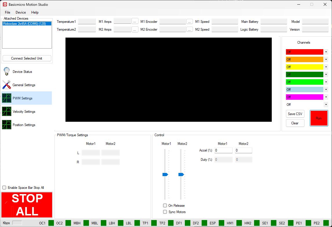
Figure 1: The motor sliders, outlined in the PWM Settings screen.
- Verify proper encoder operation. Still in “PWM Settings”, move the slider for each motor up and watch the counts in the “M1 Encoder” and “M2 Encoder” boxes at the top of the window, outlined in Figure 2. The count should increase when the motor runs in the forward direction. If it does not, power down the controller and reverse the encoder wiring at the “ENC1” or “ENC2” header for the affected channel.
Figure 2: The encoder count boxes, outlined at the top of the PWM Settings screen.
- Determine the maximum QPPS. While still in “PWM Settings”, run each motor at 100% duty and note the value shown in the “M1 Speed” and “M2 Speed” boxes at the top of the window, outlined in Figure 3. This value is the maximum QPPS (Quadrature Pulses Per Second) for that motor and encoder combination. Measure each channel individually: even identical motors and encoders can have slightly different maximums. If physical constraints prevent running a motor at full speed, use an estimated maximum encoder counts per second instead.
Figure 3: The M1 Speed and M2 Speed boxes, outlined at the top of the PWM Settings screen.
- Auto tune velocity. Select “Velocity Settings” on the left-hand side of the application to open the settings for tuning the velocity PID controller. Enter the QPPS value from the previous step in the “QPPS” box, outlined in Figure 4, making sure to use the proper box for the motor channel being tuned. Click “Tune M1” or “Tune M2” in the autotune controls, also outlined in Figure 4; the “Level” slider next to each button adjusts how aggressive the resulting tune is, from less aggressive on the left to more aggressive on the right. The motor will cycle back and forth while the controller determines the P, I, and D values, and the PID fields are filled in when tuning completes. Repeat this step for the second motor if one is attached.
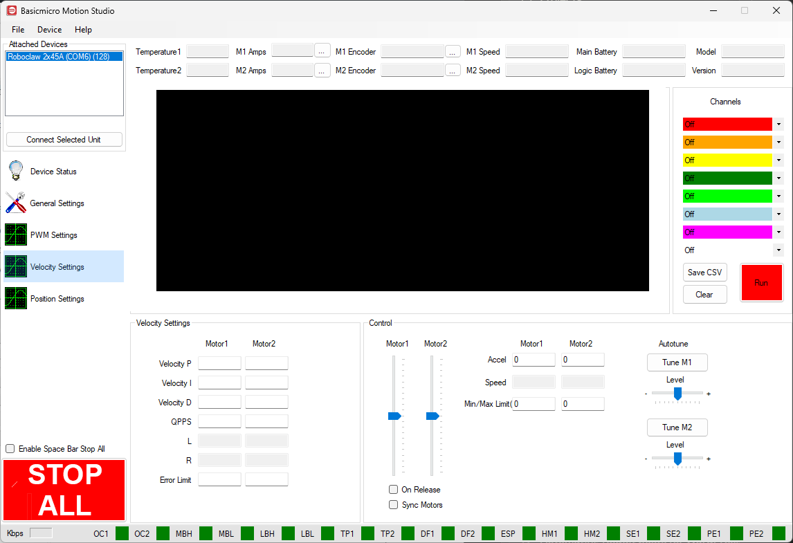
Figure 4: The QPPS field and the autotune controls, outlined in the Velocity Settings screen.
- Test the velocity controller. A first test is whether the motor operates smoothly when responding to changes: move the “Motor1” and “Motor2” sliders up and down and observe the motors. They should respond quickly and smoothly, without chatter or vibration. As a second check, use the graph above the tuning settings: set one graph channel to plot the setpoint and another to plot the speed for the motor being tested, then move the slider and watch how closely the two lines track each other. In a well tuned controller the two lines follow each other closely as the speed changes. For more on using the graph, see Graphing in Motion Studio.
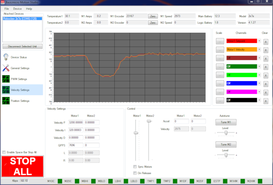
Figure 5: The graph showing motor speed tracking the setpoint. - Fine tune if needed. The PID values can be adjusted manually after auto tuning. If the tune is too aggressive, shown by vibration and chatter, lower the P and I values until the problem goes away, keeping the ratio of P to I roughly the same. If the graph shows a steady state error between the setpoint and the actual speed, increasing the I value tends to solve the problem.
- Write the settings. Click “Device” in the menu at the top of the window, then click “Write Settings” to save the tuning parameters to the controller.
Auto Tuning Position
Auto tuning for position control configures the PID values so the motor controller can move to and hold a commanded position with minimum error.
- Wire the motors and encoders, verify that they operate properly, and determine the maximum QPPS as described in steps 1 through 4 of the velocity section.
- Auto tune position. Select “Position Settings” on the left-hand side of Motion Studio to open the settings for tuning position control. Enter the QPPS value in the “QPPS” box; if velocity has already been tuned, this box will be filled in. Position auto tuning cannot measure QPPS automatically, since position systems usually have a limited range of movement. Next, select the type of auto tune to perform: “PD” uses proportional and derivative terms, “PID” adds an integral term, and “PIV” is a cascaded controller combining a velocity PD loop with a position P loop. In PIV mode both the velocity and position values are determined automatically, but QPPS must be set first. We recommend PD or PIV, as they tend to require little to no tweaking after auto tuning. Click “Tune M1” or “Tune M2” for the motor being tuned; the “Level” slider adjusts the aggressiveness of the tune. The motor will cycle while tuning, and the PID fields are filled in when it finishes. Depending on the type of tuning, some values may remain zero: this is normal.
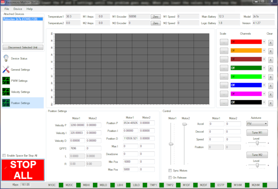
Figure 6: The position auto tune controls. 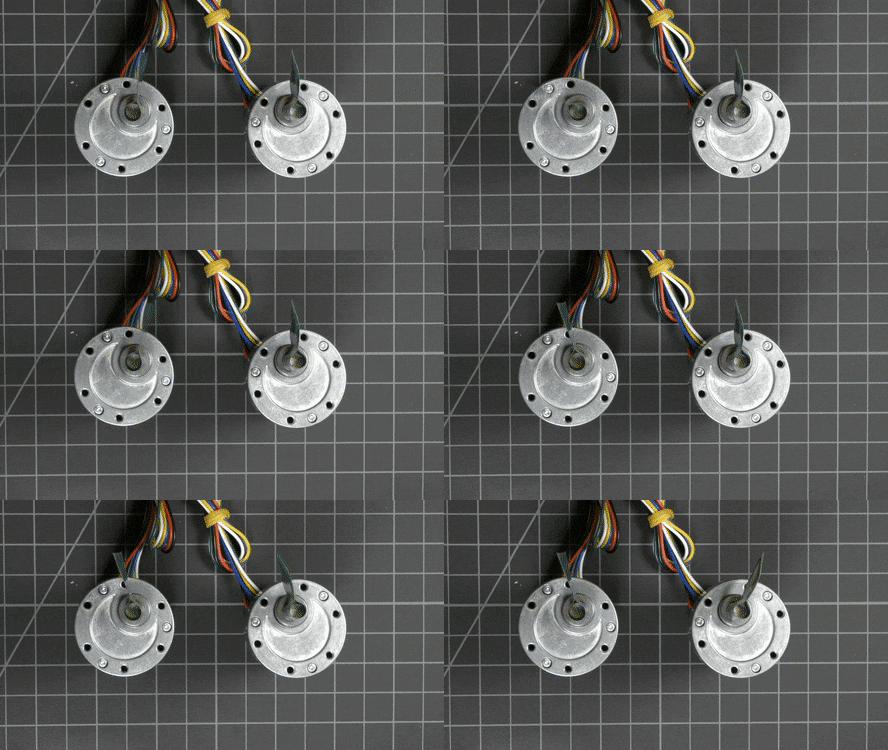
Figure 7: The motors running during auto tuning. - Test the position controller. Before testing, set values for the minimum and maximum encoder positions in the boxes below the PID fields: lower values for a small range of motion, larger values for a larger range. The “M1 Encoder” and “M2 Encoder” counts at the top of the window may also need to be zeroed before testing. Move the sliders up and down and check that the motor’s response is quick, smooth, and free of vibration or cogging. As a second check, set one graph channel to plot the setpoint and another to plot the position, then operate the sliders and watch the two lines: they should track each other with no vertical gap between them, respond together in a reasonable amount of time, and show no oscillation around the setpoint.
- Fine tune if needed. If the tune is too aggressive, shown by vibration or roughness in the motor, lower the P value for a PD tune, or lower P and I in proportion to each other for a PIV tune, until the motor operates smoothly and the graph shows no oscillation. If the graph shows a large amount of overshoot after a PD tune, increasing the D value can help.
- Write the settings. Click “Device” in the menu at the top of the window, then click “Write Settings” to save the tuning parameters to the controller.
The video below shows the complete auto tuning process in Motion Studio.
What Do the Auto Tune Error Messages Mean?
When Auto Tune cannot complete, Motion Studio stops the tuning run and shows one of the messages below. Each one points at a specific problem with the wiring, the controller, or the USB connection. Fix the cause, then run Auto Tune again.
| Error message | What it means | What to do |
|---|---|---|
| Encoder direction is reversed relative to motor direction. | The encoder counts down when the motor runs forward, so the controller cannot close the loop. | Power down the controller and reverse the encoder wiring at the “ENC1” or “ENC2” header for that channel, then confirm the count increases with forward motion as described in step 3. |
| Encoder timeout. Check encoder is operational. | No encoder counts arrived while the motor was running. | Check the encoder’s power, ground, and signal connections at the encoder header and confirm the counts change in “PWM Settings” as described in step 3. |
| Controller Error. Check Error Status. | The controller reported a fault, such as an over-current, over-voltage, or temperature condition, before or during tuning. | Check the error status reported in Motion Studio, clear the fault, and run Auto Tune again. |
| Communication Error. Please use a USB cable with shielding and Ferrite Chokes. | USB communication was interrupted during tuning, usually by electrical noise from the motors. | Use a shielded USB cable with ferrite chokes, route it away from the motor leads, and try again. |
| Error Re-Opening Comport. Try Disconnecting and Reconnecting. | Motion Studio could not reopen the serial port after the tuning run. | Unplug the USB cable, plug it back in, reconnect to the controller in Motion Studio, and try again. |
| Error Waiting for Controller. Try Disconnecting and Reconnecting. | The controller did not respond to Motion Studio in time. | Unplug the USB cable, plug it back in, reconnect to the controller in Motion Studio, and try again. |
Next Steps
The velocity and position screens used in this guide are covered in more depth in Velocity Settings in Motion Studio and Position Settings in Motion Studio. Understanding Acceleration and Deceleration Values explains the acceleration and deceleration parameters used with speed and position commands, and Velocity and Position Error Limits covers the error limits that protect against runaway motion after tuning.


