
Robots use encoders to measure how far and how fast their motors actually turn. Two motors are never perfectly matched, so wheeled robots need encoder feedback to drive straight and hold speed on slopes, while robotic arms use joint position feedback to position a gripper accurately in 3D space. A motor controller reads these signals to close the loop.
A motor without feedback runs blind: the controller applies power and hopes the mechanism does what was intended. Encoders remove the guesswork by reporting position, speed, and direction back to the motor controller. This article looks at two of the most common applications: wheeled robots and robotic arms. If you are new to encoders, Encoders Explained covers the fundamentals, including the difference between incremental and absolute types.
What Does an Encoder Do on a Robot?
An encoder converts mechanical motion or position into an electrical signal that a motor controller can read. On most robots the encoder is mounted on the drive motor, either on the rear motor shaft or built into the gearbox. With a quadrature encoder, the controller counts pulses to track relative position, measures the count rate to calculate speed, and compares the phase of the A and B signals to determine direction. With an absolute encoder, the controller instead reads a value that corresponds directly to the shaft position. Either way, the controller compares the measured values against the commanded ones and corrects the difference many times per second. On RoboClaw motor controllers, that correction is handled by PID-based closed-loop control, covered in PID Control and Motor Controllers.
RoboClaw motor controllers decode quadrature encoder signals in hardware, tracking the counts as full 32-bit values, and read analog absolute encoders directly over a 0 to 2 volt input range resolved into 2048 steps. The official Arduino, Python, and ROS 2 libraries read counts and speeds from either encoder type directly in user code.
How Do Wheeled Robots Use Encoders?
Wheeled robots use encoders for two jobs: measuring how far the robot has traveled and keeping it moving in a straight line at a constant speed. Rarely are two motors created equal. Commanded with the same power, one always spins a little faster than the other, so without encoder feedback a wheeled robot has a hard time driving straight or maintaining a constant speed through declines and inclines, load changes, and battery sag.
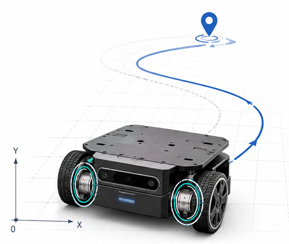
Velocity feedback reduces the drift. The controller compares each wheel’s measured speed against its commanded speed and adjusts power continuously, compensating for motor differences, changing loads, terrain, and battery state. Straight-line travel and turns become much more consistent than open-loop control can deliver, because the controller holds the commanded speed difference between the wheels.
How Encoder Odometry Measures Distance
Encoder-based distance measurement is the foundation of wheel encoder odometry. Each encoder count represents a fixed fraction of a wheel revolution, so the controller can calculate how far each wheel has traveled:
Wheel diameter:              100 mm
Wheel circumference:         100 mm x 3.1416 = 314 mm
Counts per wheel revolution: 3200

Distance per count = 314 mm / 3200
Distance per count = 0.098 mm
With 3,200 counts per wheel revolution, the theoretical resolution is about a tenth of a millimeter of wheel travel per count. If the encoder is mounted on the motor shaft before a gearbox, use the counts per wheel revolution after the gear ratio; Quadrature Encoders: How They Work shows that calculation. Actual accuracy is lower: wheel slip, tire compression, and uneven surfaces all introduce error that accumulates over distance.
On a differential-drive robot, equal travel from both wheels indicates forward motion, while a difference between the left and right wheel distances indicates a turn and is used to estimate the change in heading. Accumulating those measurements over time is wheel odometry, one of the standard forms of dead reckoning used by mobile robots, and it feeds navigation software such as the ROS 2 differential drive controller.
Quadrature encoders are directional. On a mirrored differential-drive setup, verify that both encoder counts increase when the robot is commanded forward; if one counts in the opposite direction, reverse its A and B signal connections. Correct motor and encoder polarity is required for mixed drive and closed-loop control to operate properly.
How Do Robotic Arms Use Encoders?
Robotic arms depend on accurate joint position feedback. Absolute encoders are a natural fit for arm joints because a properly selected encoder can report the joint angle immediately after power-up, without a homing move, even if the arm was moved while power was off. Quadrature encoders work well too and often cost less, but they measure movement relative to a reference count rather than the joint’s physical position, so systems that need a known position after startup typically home each joint to a limit switch, index mark, or other known reference before motion begins. The tradeoffs between the two types are covered in Encoders Explained. In either case, position limits should be set inside each joint’s physical travel range, with a safety margin before the mechanical stops, to reduce the risk of driving a joint into a hard stop or another part of the arm. The same position control approach applies to linear actuators, gearmotor-driven grippers, and pan-and-tilt mechanisms.
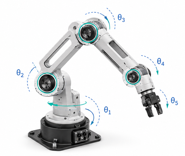
Joint position feedback is also essential when an arm executes motions calculated with inverse kinematics. Given a desired gripper position in 3D space, inverse kinematics computes the joint angles needed to reach it, and the controller then uses encoder feedback to drive each joint to its commanded angle and hold it against gravity and load. If a joint is unhomed or its reported position is wrong, the controller’s estimate of the arm’s configuration is wrong, and the gripper may miss its intended position. Absolute encoders are particularly useful here because the joint positions are known the moment power is applied; a properly homed quadrature encoder provides equally valid feedback once the homing move is done.
How Does a Motor Controller Use Encoder Feedback?
The motor controller is where encoder signals become motion. RoboClaw controllers support three closed-loop modes: velocity control, position control, and a cascaded mode that combines position with velocity. Supported feedback devices are quadrature encoders, analog absolute encoders that output 0 to 2 volts, and potentiometers.
Once the encoder is connected, the control loop must be tuned so the motor responds accurately and smoothly to the feedback. The auto-tune function in Motion Studio measures the motor and encoder combination and produces working PID values, and it typically gives usable results with quadrature encoders. The key parameter is QPPS, the maximum quadrature pulses per second the motor and encoder can produce, found by running the motor at 100% duty and reading the encoder speed. Auto Tuning with Motion Studio walks through the procedure.
Encoder feedback is available across the entire line of RoboClaw motor controllers, from the dual-channel 2x7A up to single-channel 300A models, so the same closed-loop setup scales from a desktop robot to a heavy platform. The table below summarizes where encoders fit on a typical robot.
| Application | What the encoder provides | Control mode |
|---|---|---|
| Drive wheels | Straight tracking, speed under load, distance traveled | Velocity control |
| Robotic arm joints | Joint angles for 3D positioning, held against load | Position or cascaded control |
| Linear actuators | Position within the travel range | Position control |
| Pan-and-tilt mechanisms | Pointing angle and smooth motion | Position or cascaded control |
Next Steps
Pololu Encoder Wiring shows how to connect a typical hobby encoder to a RoboClaw. Once wired, Using Encoders with the Arduino Library and Using Encoders with the Python Library cover reading counts and speeds in code, and Auto Tuning with Motion Studio gets velocity and position control tuned and running. For a deeper look at the signals themselves, Quadrature Encoders: How They Work breaks down the A and B channels in detail.


