
Richard Hopkins built a fully working K9 robot dog from Doctor Who, driven by two 24V scooter motors under a RoboClaw 2x15A motor controller with custom encoder wheels. A Raspberry Pi commands the RoboClaw and coordinates LIDAR, infrared, and ultrasonic sensors, a camera, moving ears and tail, and a speaker.
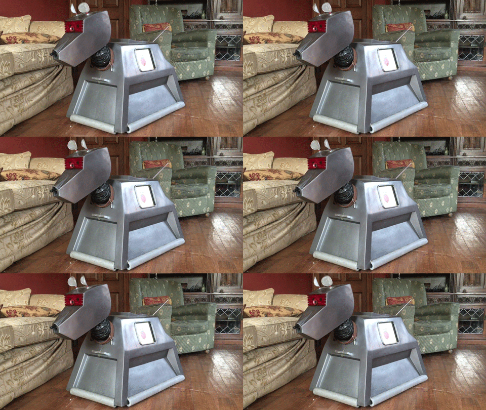
A robot builder by the name of Richard Hopkins is building a complex robotic dog inspired by the one from Doctor Who. Richard calls his creation “K9”, just like the original. K9’s body is made from fiberglass and painted grey to match the television prop. For propulsion K9 uses a pair of 24V scooter motors, and a ball caster supports the other end of the dog. The two scooter motors are controlled by a RoboClaw 2x15A motor controller. Richard created custom encoder wheels for each motor, and the RoboClaw decodes them to provide accurate control of both drive wheels.
How Is K9 Built?
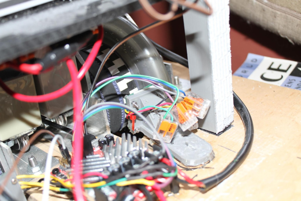
At the core of K9 is a metal chassis that houses the main components of the robot. The drive wheels are mounted to the chassis, and the bulk of the electronics are housed there as well. The drive system is powered from a pair of 12V 2.1Ah batteries wired in series to provide 24VDC, with a separate 12V battery for the logic. Contained in the chassis is the brain of the robot: a Raspberry Pi single board computer. The Raspberry Pi sends commands to the RoboClaw for movement and communicates with the other hardware inside K9. Small Espruino microcontroller boards handle the ears, the rear sensors, and the follow-me function, and an Adafruit 16-channel servo board drives the tail, the lights, and the screen.

Key Features
- Two 24V scooter motors with custom encoder wheels, driven by a RoboClaw 2x15A motor controller
- Raspberry Pi main computer with Espruino microcontrollers for the ears, rear sensors, and follow-me function
- Two LIDAR units in the ears, swept back and forth by servos to scan the surroundings
- Five infrared proximity sensors and five ultrasonic receivers for navigation and obstacle avoidance
- Camera in the head for a live video feed, plus a microphone and speaker
- Moving tail, eye lights, and a TFT screen driven through a 16-channel servo board
K9 is packed full of sensors. For navigation and obstacle avoidance it features a large number of infrared and ultrasonic sensors. The ears also contain a pair of LIDAR units for longer range and more fine-grained sensing of the environment, and the ears are swept back and forth by servos to scan the area around K9. A camera in the head provides a live video feed from the robot, and the head also holds a microphone and speaker.
In addition to the moving ears, K9 has a moving tail and eyes that light up. The onboard speaker allows K9 to communicate with the outside world. In short, K9’s builder has done everything he can to make his build as faithful to the original as possible.
The video below shows an early test of the motors and the RoboClaw.
Next Steps
Richard’s K9 build website is worth exploring. He has extensive details on every aspect of the build as well as downloadable plans, so you can build one of your own. We thank Richard for documenting his build and for choosing a RoboClaw motor controller.
To build a similar drive system, the RoboClaw 2x15A motor controller handles a pair of scooter-class motors with encoders. Packet Serial with the Raspberry Pi 3 covers connecting a Raspberry Pi to the RoboClaw, and Using Encoders with the Python Library shows how to read encoders and run closed-loop speed control from Python.


