Motor Specifications

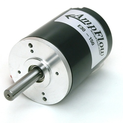
Figure 1: A brushed DC motor, like the those used with the RoboClaw and MCP.
A DC brushed motor has several specifications, three of which are key to properly pairing a motor controller.
The first specification is the motor’s operating voltage. The motor controller must be able to operate within the correct voltage range for the motor to avoid damage.
The second specification is running current. Typical this is the required current at specific voltage to spin a motor at it’s maximum speed under no load.
The stall current, which is the key specification to properly pairing a motor controller. Any DC brushed motor when not rotating is in a stall condition. Depending on the voltage the motor is operated at, the stall current will vary. The higher the voltage, the higher the stall current. This value is determined by the motors coil resistance and Ohm’s law I=V/R. A given motor with a stall current of 100Amps at 12VDC will have a higher stall current requirement at 24VDC.
Selecting a Motor Controller
Often manufacturers do not publish the motor’s stall current and only provide the running current, leaving it up to the end user to determine the stall current. With the motors coil resistance and using Ohms law (I=V/R), the stall current can be determined. We often see customers attempting to pair a motor with an under powered motor controller due to this. Another assumption we often see is the motor will operate at light loads and therefore can use a smaller motor controller. This is typically not the case. When starting from a stand still the motor can require maximum stall current in order to startup and spin. The starting load and operating voltage will determine the maximum current is required. Once the motor is spinning freely the current will drop proportionally. However, if the motor direction is changed without a full stop the maximum stall current can easily be reached. The stall current will also vary during direction changes based on load, potentially increasing the total current required to reverse direction.
An example of this would be a DC brushed motor that has a stall current of 100 amps, a running current of 15 amps and an operating voltage of 12VDC. The RoboClaw 2X30 has the running current to run this motor. However, since the RoboClaw 2X30 is only capable of 60 amps for brief periods it may not be able to maintain the motors speed properly due to the total current requirements.
Based on the example above the RoboClaw 2X60A which is rated at 120 amps peak for brief periods and 60A continuous would be a more effective solution to running our example motor. The 2X60A can handle frequent starting and stopping along with sudden direction changes. The only limitation being the heat which the motor controller will generate. This is where adequate cooling is critical, especially if the motor is expected to be under heavy loads and change direction frequently.
Depending on load and voltage the RoboClaw 2X60 may be too small for our example motor and a higher current rated RoboClaw motor controller would be required.
