Introduction
The RC mode of the RoboClaw motor controller allows an RC transmitter and receiver to control both motor channels of a RoboClaw. Each motor can be operated independently or mixing can be enabled to allow for a differential drive scheme. This Application Note walks through the process of connecting the hardware and programming the RoboClaw with the onboard buttons.
Materials
Things you’ll need for this tutorial:
- (1) RoboClaw motor controller
- (2) motors
- (1) radio transmitter
- (1) radio receiver
- (1) battery for RoboClaw
- (2) female to female servo cables
- (1) small screwdriver
Let’s get started
1. First we will begin by wiring the motors to the RoboClaw. Locate the terminals labeled M1A and M1B. Loosen the screws on these terminals before you begin wiring. Wire the first motor to the terminals labeled M1A and M1B by placing one end of the bare wire in each terminal and tightening the screws with your screwdriver until the connection is snug. Note that the order of wiring does not matter for the first motor.
2. The second motor is wired to the terminals labeled M2A and M2B. The order of wiring does matter for this motor. Look at the first motor you wired and note what color wire you wired to the M1A terminal. Connect the same colored wire of the second motor to the M2A terminal. Lastly, connect the final wire of the second motor to the M2B terminal. Make sure that your motor wire connections are secure and do not come loose from the terminals.
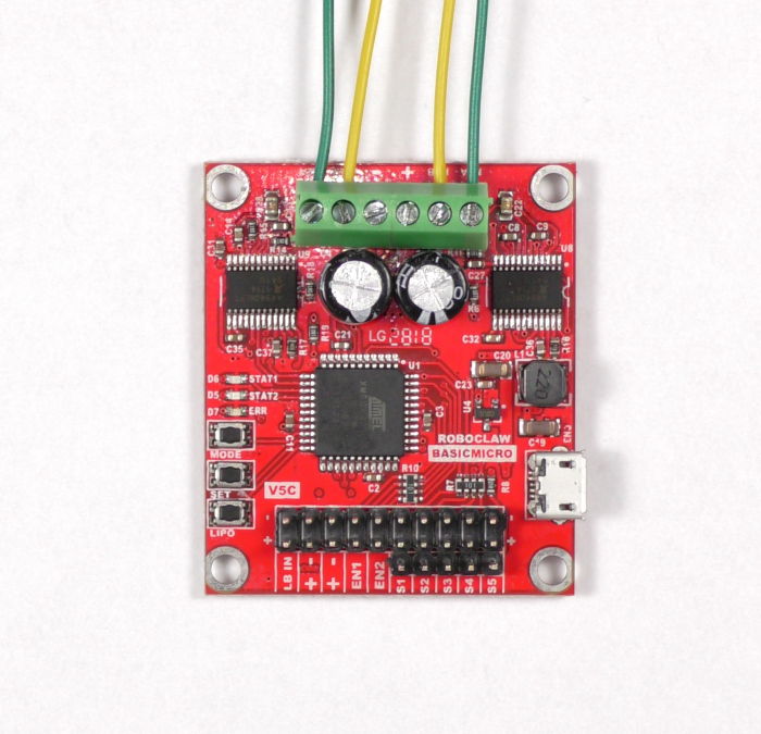
Figure 1: Two motors wired to the RoboClaw properly.
3. Now we will attach one channel of the receiver to the RoboClaw. Located the pin header labeled S1, this is where we will connect the output from the radio receiver. Also, using the receiver’s manual find the connection for the throttle channel. Using a servo cable connect the throttle channel to S1. Note that the connections at the receiver and RoboClaw are both polarized. On the RoboClaw the negative pin of S1 is towards the inside of the board. The polarity on the receiver varies by model and is labeled on some receivers.
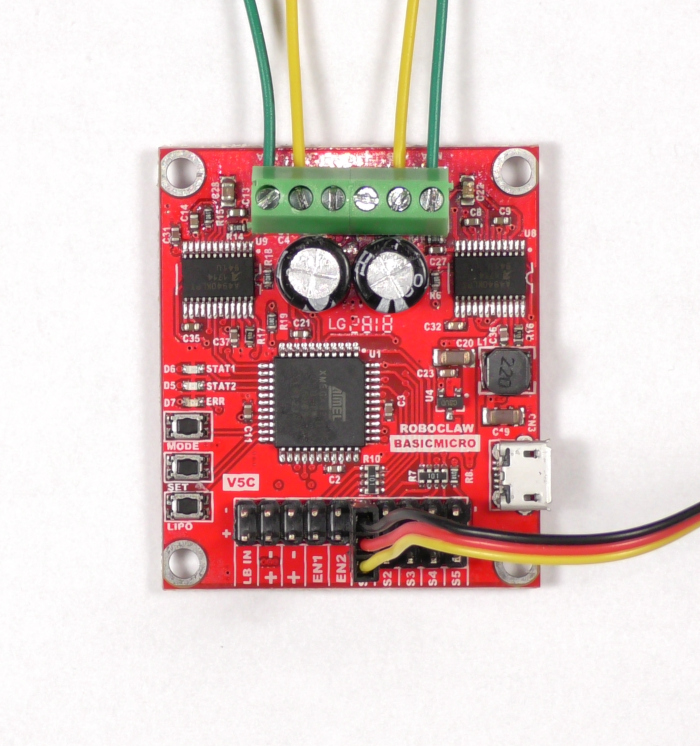
Figure 2: One RC channel connected.
4. Located the pin header labeled S2. Connect the aileron channel of the receiver to S2 as you did with the throttle channel. Remember to observe proper polarity.
Note that the RoboClaw will power the receiver from the onboard BEC. If the receiver is being powered by an external battery or the BEC of another speed controller the 5V lead on the servo cables must be cut or removed entirely. This prevents a conflict between voltage sources.
RoboClaw BEC Powering the Receiver
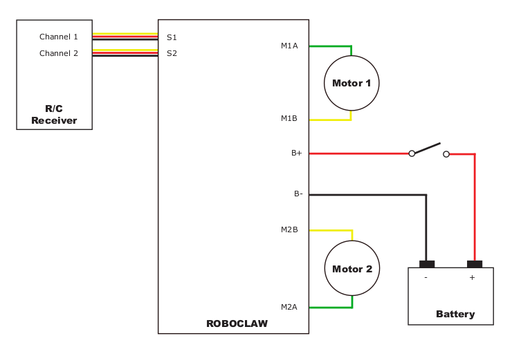
Figure 2: In this wiring configuation the 5V line is connected between the RoboClaw and receiver. The RobClaw powers the receiver.
Receiver with External Power
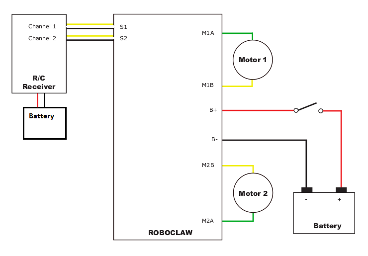
Figure 2: In this wiring configuration the receiver is powered extenally and the 5V line between the RobClaw and receiver has been removed.
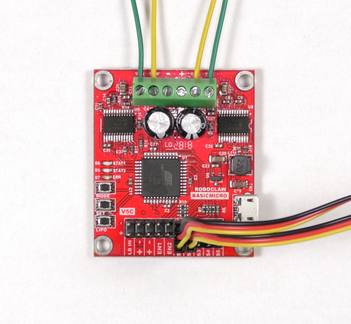
Figure 3: Two RC channels connected to the RoboClaw.
5. Identify the positive and negative leads of your battery. There are two screw terminals on the RoboClaw labelled + and -. Find these terminals and loosen the screws on them. Attached the negative lead first by placing the lead in the loosened terminal and tightening the screw down until the connection is snug. Repeat this step with the positive lead.
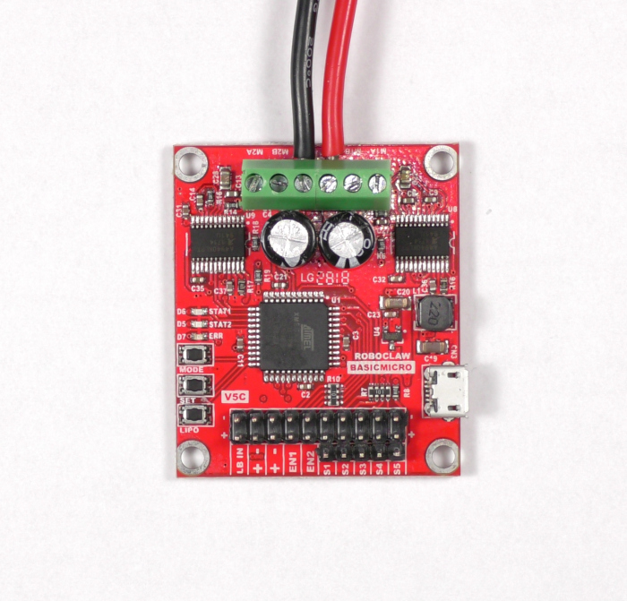
Figure 4: Power wired properly to the RobClaw.
6. Turn on your radio transmitter.
7. If you need to bind your receiver please do it now while power is applied.
8. Locate the three buttons on the board labeled MODE, SET and LIPO. These buttons will be used to configure the settings for the RoboClaw. Also note the three LEDs labeled STAT1, STAT2 and ERR, these will are used for feedback while using the buttons.
In this step the RC control mode will be configured with the onboard buttons. There are two possible variants of RC control. The first is where two RC channels each control a motor independently. The second control mode applies mixing so that one channel operates both motors in the forwards and backwards direction while the second channel enables left and right steering with both motors.
Press and release the MODE button. The STAT2 LED will blink a number of times to indicate what mode it is in. Press the SET repeatedly until the STAT2 LED blinks either once for the first version of RC control or twice for RC control with mixing. Press and release the LIPO button to save the settings.
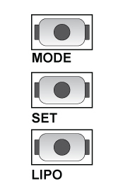
Figure 5: The buttons for configuring the RoboClaw.
Figure 6: Setting RC mode with mixing.
9. Test that the motors are responding properly to each radio channel input. If mixing has not been set the throttle and aileron input should operate each motor seperately. If mixing has been enabled throttle input should move both motors backwards and forwards and aileron input should cause the motors to turn in opposite directions.
Note: Loss of signal between the RC transmitter and receiver, either due to range or turning the transmitter off, can result in issues with the control of a robot. Many receivers will continue to send the last know stick positions to the RoboClaw. This can result in a robot running away or crashing. Some radio and receiver combinations can be programmed with failsafe positions to prevent these problems from occurring. Consult the documentation for the system being used for further details.
Conclusion
If the throttle and aileron channels are not the desired controls for the motor channels they can be changed by moving around the servo connections on the receiver. The servo connections to the RoboClaw remain the same, however note that motor channel 1 is associated with the S1 header and motor channel 2 is associated with the S2 header.