Often when using a RoboClaw or MCP motor controller multiple devices are attached to the controller, these may include microcontrollers or a PC connected via USB. A condition known as a ground loop may occur and it has the potential to destroy attached devices if power is improperly disconnected. To properly power down a motor controller such as RoboClaw or MCP the battery positive terminal should always be removed first.
A ground loop can occur when several interconnected devices share a common ground creating multiple paths to ground. Current can flow along paths that are not desirable. With motor controllers the worst case scenario occurs when a ground path for the primary power supply is removed and another path exists at the same time. When this happens current flows from the battery or power supply through components that are not rated for large amounts of current, often destroying the attached device.
One example where this can occur is when a RoboClaw or MCP being powered from a power supply plugged in to a wall outlet is being controlled from a PC with a USB connection. When using a USB connection from the PC to the motor controller there is a ground connection between the PC and the motor controller due to the USB connection. If the negative lead of the power supply is disconnected power can flow from the USB port of the computer to the control circuitry of the motor controller. This can result in destroying the USB port of the computer as well as the motor controller. To avoid this particular situation during development its recommend to use a USB isolator.
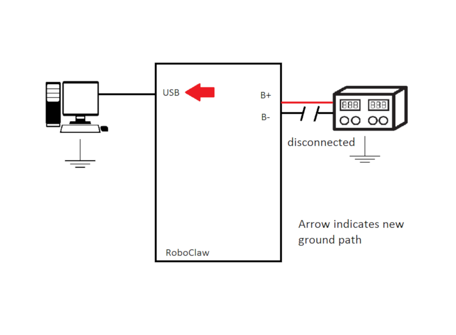
Figure 1: Diagram showing the new ground point after the main power source ground is disconnected.
Another problematic situation is when a microcontroller is attached to the motor controller and both the microcontroller and motor controller are powered from the same battery source. The microcontroller has a direct ground connection back to the battery as well as a second signal ground to the motor controller. When the ground connection to the main power source is removed the signal ground from the attached microcontroller becomes the new ground and a large amount of current will flow in places where it will cause damage.
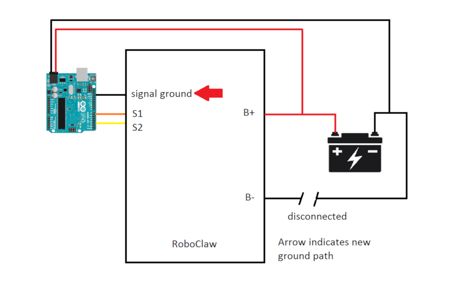
Figure 2: Diagram showing the new ground point after the main power source ground is disconnected..
Finally, the general issue occurs when there is a second ground return path to the primary power source that allows current to flow when the ground from the power source is removed. Any device attached to the motor controller as well as the motor controller itself can see a large amount of current flow through it and likely cause damage.
Preventing Grouding Issues
There are several ways to prevent the previously discussed problems from occuring. The list below, if followed, should prevent damage to the motor controller and attached components.
1. When disconnecting the main power source do not remove the negative connection. Remove the positive connection first.
2. Ensure that the power connections to the board are solid and will not come loose in any way. If the negative connection comes loose the problems discussed in this app note may occur.
3. Power external hardware from the battery eliminator circuit (BEC) built in to the motor controller. If a BEC is available on the motor controller and provides the voltage and current necessary for external hardware, use it instead of a separate power source.
4. Power external hardware from a separate battery. Using a separate battery for external hardware prevents the creation of an additional return path back to the primary power source.
5. Use a USB opto-isolator when communicating to a motor controller over USB. This includes using a PC, laptop or microcontroller such as a Raspberry Pi.
Proper Wiring Diagrams
Below are diagrams that show two scenarios with proper wiring that prevents the issues discussed above. In the first diagram a USB isolator is used to prevent the USB connection from becoming a new ground path when using a desktop PC. In the second diagram an attached microcontroller is powered from the battery eliminator circuit (BEC) on a RoboClaw. When using the BEC a second ground path is not created when a microcontroller is attached because the BEC shares its ground with all of the other ground points on the motor controller.
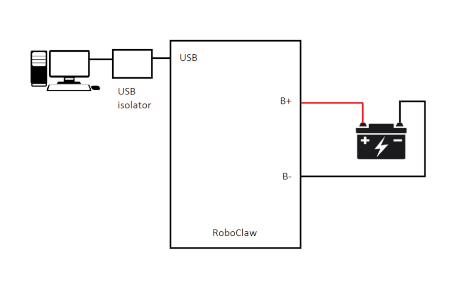
Figure 3: Diagram showing the correct wiring when using a USB connection to a motor controller.
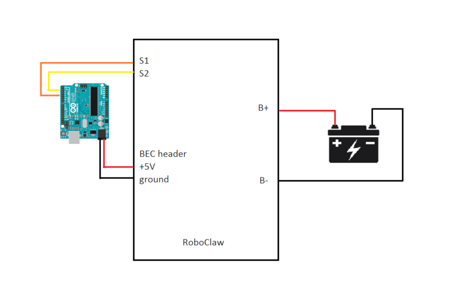
Figure 4: Diagram showing the correct wiring when using a microcontroller with a motor controller.