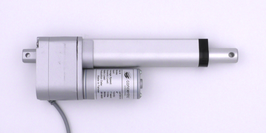
Figure 1: The linear actuator used in the Application Note.
Linear actuators are commonly used in robotics project and serve a variety of purposes. The RoboClaw motor controller can easily be used to drive these motors and use the feedback from them for precise position control. This Application Note covers how to connect them to a RoboClaw motor controller and tune them for position control.
(1) roboclaw motor controller
(1)
linear actuator
(1) soldering iron
(1) solder
(1) resistor (value varies, see below)
(1) capacitor (0.01 – .1 uF)
(3)
0.1″ female crimps
(3)
0.1″ female crimp connector housings
(1) crimper
(1) wire stripper
(3) pieces of heat shrink
(1) computer with BasicMicro Motion Studio installed
(1) micro USB cable
(1) small screwdriver
Signal Line Noise
A problem with many linear actuators, including the one used in this app note, is that the wires for the motor’s power are close to or directly alongside the wires for the feedback system. When a PWM (pulse width modulated) power signal is sent to the motor noise from the power wires couples to the feedback wires producing a noisy output signal. This noise is then read by the microcontroller or motor controller as an erratic signal rather than a steady voltage. This makes it difficult or impossible for the controller to determine the exact position of the actuator. If the controller uses the noisy position data as part of a feedback loop the actuator can operate erratically or not at all.
To solve the noise issue a capacitor can be added across the signal and ground lines from the feedback system. The capacitor smooths out the signal producing something closer to a steady voltage output. However the capacitor must be sized appropriately our else a signal delay can be introduced to the output. When using a RoboClaw with a system that had an analog output a capacitor between 0.01 and 0.1 uF is recommended.
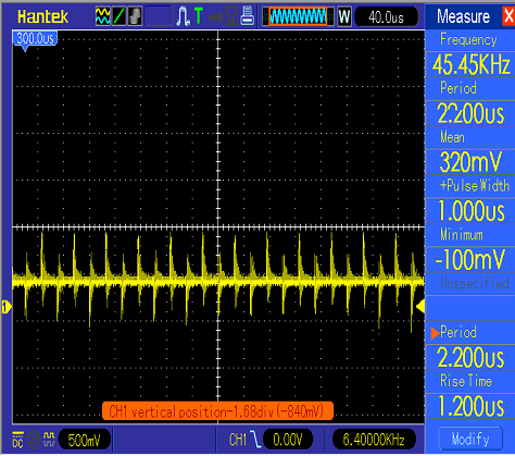
Figure 2: An oscilloscope view of a noisy signal line.
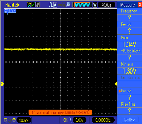
Figure 3: A oscilloscope view of the same signal line as shown in the previous image but with a capacitor applied between the signal and
ground lines.
Analog Compatibility
Another consideration when using an analog encoder output, like the one on most linear actuators, is the voltage range of the feedback system. The RoboClaw’s analog encoder input expects to see a signal between 0 and 3.3 volts. The encoder power pins on the RoboClaw supply 5 volts so that almost all encoders will work with it. To bring the potentiometer output within range a resistor is added to the power lead of the potentiometer wiring to create a voltage divider. A look up table has been provided below to determine the value of resistor need for a given potentiometer value.
Prepare Connections
1. Cut off the supplied power connector and strip off a small section of the insulation on both power wires.
2. Cut off the connector for the potentiometer wiring. Strip the ends of all three potentiometer wires. Using the crimper crimp a female pin on each wire. Finally put a female connector of each wire being sure to align the hole in the connector with the tab on the pin.
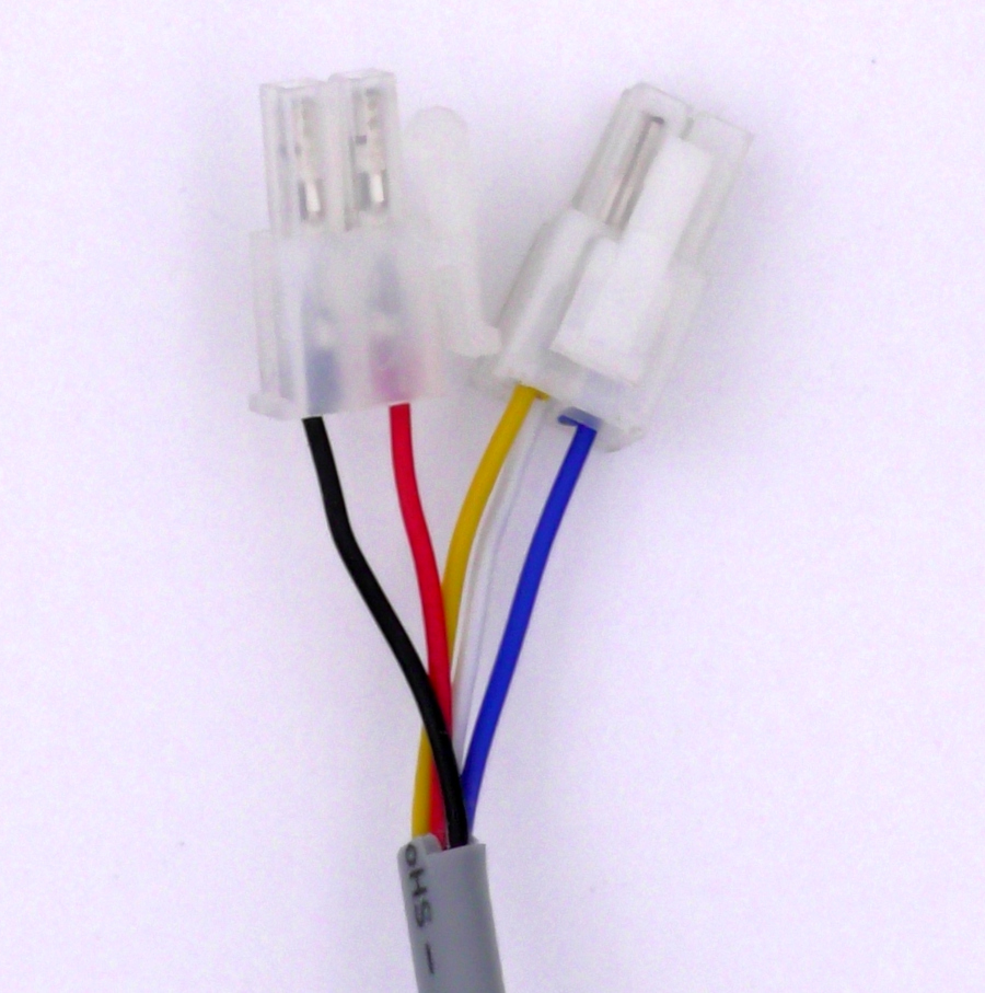
Figure 4: The original connectors for power and feedback.
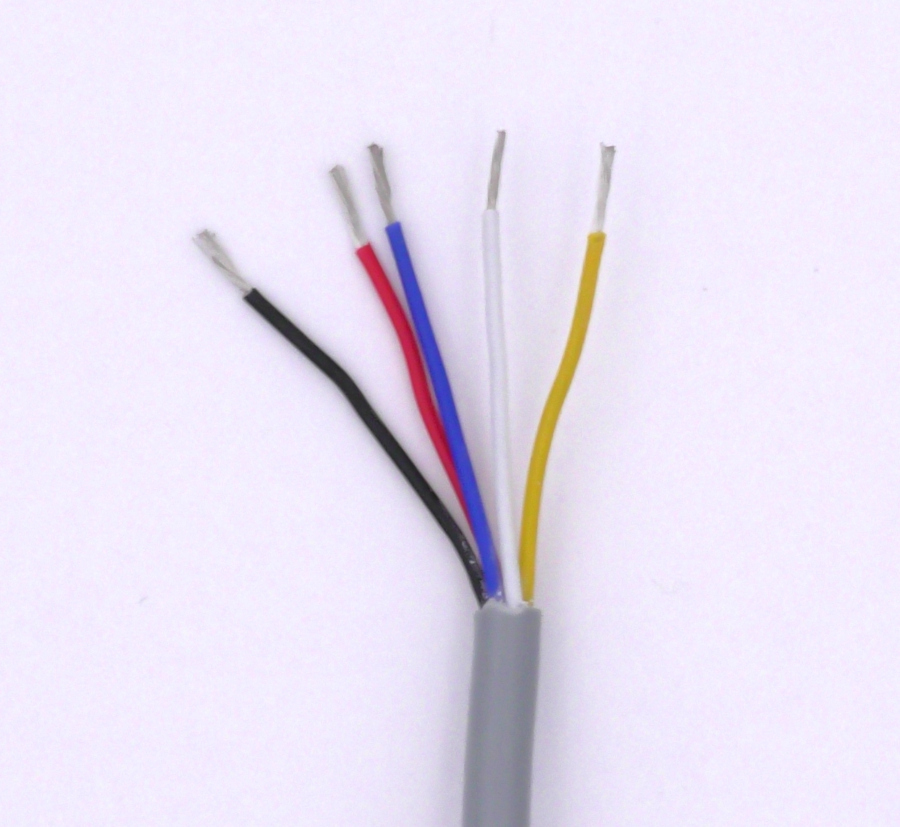
Figure 5: All connections cut and stripped.
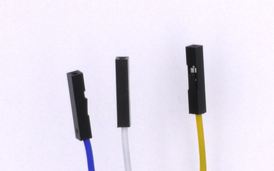
Figure 6: The connectors added to the ends of the wiring harness.
Install Components
1. Cut the power lead of the potentiometer wiring in half and strip the resulting ends. Solder the correct sized resistor in between both ends of the cut and stripped wiring. The resistor needed can be found by measuring the total resistance of the potentiometer in the actuator and multiplying the value by 1.5. To find the resistance of the potentiometer use a multimeter to measure the resistance between ground and the power leads of the potentiometer wiring.
|
Potentiometer Resistance |
Resistor Value |
|
500 ohms |
750 ohms |
|
1k ohms |
1.5k ohms |
|
2k ohms |
3k ohms |
|
5k ohms |
7.5k ohms |
|
10k ohms |
15k ohms |
|
22k ohms |
33k ohms |
|
47k ohms |
70k ohms |
|
50k ohms |
75k ohms |
|
100k ohms |
150k ohms |
|
220k ohms |
330k ohms |
|
470k ohms |
700k ohms |
|
500k ohms |
750k ohms |
|
1M ohms |
1.5M ohms |
2. Cut the signal and ground lines of the potentiometer wiring in half and strip the resulting ends. Solder them back together leaving an exposed area where the ends of the capacitor can be soldered on. Once both wires have been soldered back together solder a leg of the capacitor to each wire’s solder joint. The capacitor should we soldered in so that it connects the signal and ground lines.
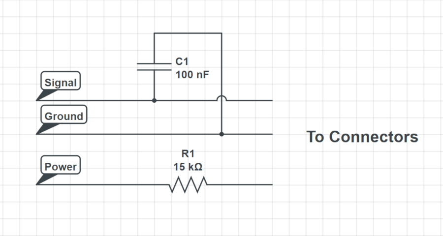
Figure 7: Schematic showing how the additional components are wired to the wiring harness.
3. Place heat shrink over the exposed sections of each wire and heat it up until it shrinks down over the soldered connection.
Connect the Actuator
1. Connect the power leads of the actuator to the motor channel 1 terminals of the RoboClaw motor controller.
2. Conect the potentiometer leads of the actuator to the pin header of the RoboClaw using the table below as a reference.
|
Function |
Potentiometer |
RoboClaw |
|
Power |
Power lead |
Encoder power header positive pin (see markings on board) |
|
Ground |
Ground lead |
Encoder power header ground pin (see markings on board) |
|
Signal |
Signal lead |
Encoder 1 header A pin (closest to board edge) |
Configure in Motion Studio
1. Power up the motor controller by connecting power to the it with a power supply or battery.
2. Connect the motor controller to a computer with a micro USB cable.
3. Open Motion Studio on the computer and click “Connect Selected Unit” to connect the controller in the application.
4. Navigate to the “General Settings” window and find the pane labeled “I/O”. Set “Encoder 1 Mode” to “Absolute”.
5. Find the pane labeled “Battery”. Select “Use User Settings” from the dropdown labeled “Battery Cutoff”. Set “Max Main Battery” to one volt above the power source’s voltage and “Min Main Battery” to one volt below the power source’s voltage.
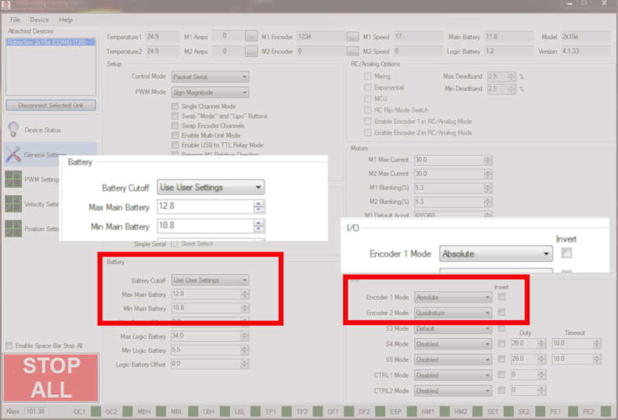
Figure 8: Location where encoder and battery settings are configured.
Test the Actuator
1. In the “PWM Settings” windows use the slider for motor channel 1 to drive the actuator’s motor back and forth. In the motor does not move in the desired direction when moving the slider up power down the controller and reverse the motor connections at the screw terminal.
2. Move the channel 1 motor slider up and note the direction the encoder is counting in the “M1 Encoder” box at the top of the application. The encoder should count in a positive direction. If the encoder is not counting in the proper direction power down the controller and move the potentiometer signal line to the other pin on the encoder 1 header.
Tune for Position Control
The final step in setting up a linear actuator with a RoboClaw is tuning for position control. Position control allows for precisely setting the distance the acutuator moves in or out and is repeatable over time.
1. Navigate to the “PWM Settings” window and use the slider to run the actuator at full speed. While doing this note the value in the “M1 Speed” box at the top of the application. This value will be used for tuning the system.
2. While still in the “PWM Settings” window use the slider for motor channel 1 to move the actuator to it’s minimum and maximum positions. At both points note the value in the “M1 Encoder” box at the top of the application. These values will also be used for tuning the system.
3. On the left-hand side of the application navigate to the “Position Settings” window. In the box labeled “QPSS” enter the value found in the last step.
4. Locate the boxes labeled “Min Pos” and “Max Pos” and enter the encoder values found earlier for the minimum and maximum actuator position.
5. Enter a test value in the box “Position P” in the “Motor 1” column and then test the smoothness of the actuator’s movement by moving the slider up or down. If the movement is jerky or rough lower the value entered earlier, if the movement is smooth but doesn’t stop immediately after stopping the slider increase the value entered earlier. Continue this process until the actuator moves smoothly and stop when it is supposed to stop without any under or overshoot.
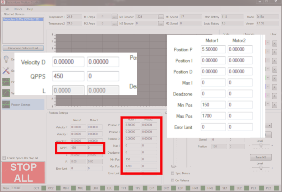
Figure 9: The locations where values are entered for position control tuning.
Figure 10: A linear actuator being driven by a RoboClaw motor controller.