
Hardware serial is the most reliable way to connect an Arduino to a RoboClaw motor controller, and on ARM-based boards like the Uno R4 it is the only option. To use it, pass a pointer to your board’s serial object, such as &Serial1, to the Basicmicro constructor, then call begin() with the baud rate set in Motion Studio.
Serial communication is one of the many control methods that can be used with the RoboClaw motor controller, and most microcontrollers include serial ports as part of their set of peripherals. On an Arduino there are two common ways to use serial: one uses the actual serial port hardware built into the microcontroller, and the other uses software to emulate a serial port. This application note covers using the hardware serial ports of Arduino boards with the Basicmicro Arduino library, which port names each board defines, and when software serial is the more practical choice.
Why Use Hardware Serial?
Software serial has one advantage: it can use pins other than the dedicated serial pins. Beyond that, hardware serial is the better option in most scenarios. Software serial depends on precise timing done in software, and it becomes unreliable as the baud rate climbs; 57600 bps is a practical ceiling, and rates above that cannot be trusted. Software serial also relies on interrupts, which can interfere with other interrupts used in a sketch, including ones used inside any library the sketch includes, causing them to be missed and the sketch to misbehave. Finally, the SoftwareSerial library is only available on AVR-based boards like the Uno and Nano.
Hardware serial has none of these limitations. It uses a dedicated UART peripheral in the microcontroller, runs reliably at every baud rate the RoboClaw supports, does not tie up interrupts, and is available on every Arduino model. On ARM-based boards, including the Uno R4, Due, GIGA, and the MKR and Nano 33 families, SoftwareSerial does not exist at all, so hardware serial is the only way to communicate with a RoboClaw.
Which method to use comes down to the board. On a classic Uno or Nano the single hardware serial port is shared with the USB connection, so using it means disconnecting USB and giving up the serial monitor while the sketch runs; on those two boards, software serial on any pair of pins at 57600 bps or below is often the more practical choice. For a worked example using software serial on an Uno, see Using Encoders with the Arduino Library. On every other model, hardware serial is the recommended method.
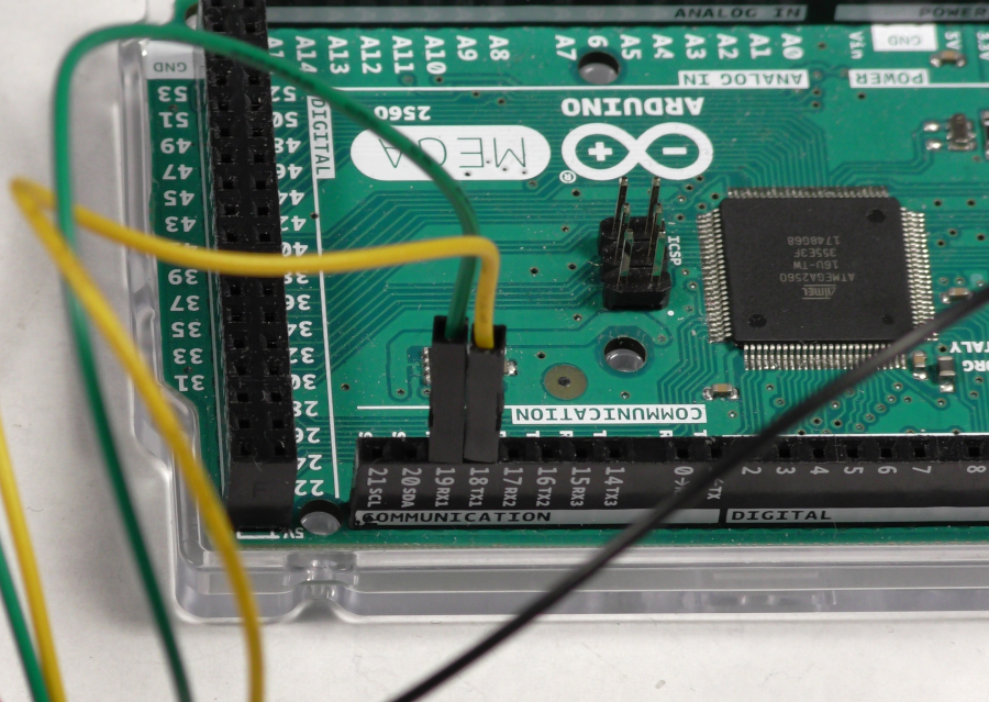
Some Arduino models, like the classic Uno and Nano, have their only hardware serial port wired to the USB to serial adapter built into the board. On those boards the USB connection must be disconnected to run a sketch that uses hardware serial to communicate with the RoboClaw. Boards with a separate USB port, like the Uno R4 and Leonardo, and boards with multiple hardware serial ports, like the Mega, can leave USB connected for the serial monitor while another port talks to the RoboClaw.
Which Pins Does Hardware Serial Use?
Unlike software serial, hardware serial must use the dedicated serial pins; they are the only option in this mode. The hardware serial pins are labeled on the Arduino board as “RX” and “TX”. If the board has more than one hardware serial port, the RX and TX labels are also numbered to show which port they belong to.
Which Serial Object Does Your Board Define?
The Arduino core defines a serial object for each hardware serial port a board has, but the names are not the same on every model. The port connected to USB is always named Serial. The name of the port on the dedicated RX and TX pins varies: on a classic Uno or Nano it is the same shared Serial port, while boards with a separate USB connection, like the Uno R4, Leonardo, and Micro, name their dedicated port Serial1 even though it is the board’s only hardware UART. The table below lists the port names for common models.
| Board | Hardware serial ports | Connecting a RoboClaw |
|---|---|---|
| Uno R3, Nano, Mini | Serial on pins 0 (RX) and 1 (TX), shared with the USB adapter |
Use Serial and disconnect USB while the sketch runs |
| Uno R4 Minima, Uno R4 WiFi | Serial1 on pins 0 (RX) and 1 (TX); Serial is the USB connection |
Use Serial1; USB can stay connected |
| Leonardo, Micro | Serial1 on pins 0 (RX) and 1 (TX); Serial is the USB connection |
Use Serial1; USB can stay connected |
| Mega 2560, Due | Serial on pins 0 (RX) and 1 (TX), shared with USB; Serial1 on 19 (RX) and 18 (TX); Serial2 on 17 (RX) and 16 (TX); Serial3 on 15 (RX) and 14 (TX) |
Use Serial1, Serial2, or Serial3 and keep Serial for the serial monitor |
| Other models | The USB connection is always Serial; dedicated serial pins are usually Serial1 and up |
Check the board’s documentation for the port names and pins |
How Do You Use Hardware Serial with the Library?
The code below communicates with the RoboClaw using packet serial. Before running your Arduino code, connect the RoboClaw to Motion Studio and set it to Packet Serial mode, and note the address and baud rate configured there. The values used in your sketch must match the controller’s settings.
- Include the Basicmicro library at the top of the sketch. If the library is not installed yet, it is available in the Arduino Library Manager; see Using the RoboClaw Arduino Library for the install steps.
// Include the Basicmicro library #include <Basicmicro.h> - Use one of the predefined hardware serial objects. When using hardware serial there is no need to create a serial object; the Arduino core defines one for each hardware serial port the board has. Use the name your board defines for the port wired to its RX and TX pins, as listed in the table above.
Serial // The port connected to USB on every board Serial1 // The dedicated serial port on most boards Serial2 // Additional ports on boards like the Mega 2560 Serial3 - Create the Basicmicro object. Pass a pointer to the serial port being used, not simply its name, by putting an ‘&’ character in front of the serial port’s name; the program will not work properly without it. The second parameter is the timeout value for serial communication in microseconds.
// 10000 microseconds = 10ms serial read timeout Basicmicro roboclaw(&Serial1, 10000); - Start serial communication by calling the
begin()function on the Basicmicro object. The only parameter is the baud rate, which must match the baud rate set on the RoboClaw with Motion Studio.// Call the begin function passing it the baud rate for serial comms roboclaw.begin(38400); - Call functions on the Basicmicro object to control the motor controller. Any function in the library can now be used.
// Run motor 1 in the forward direction at about 30% duty cycle
roboclaw.DutyM1(0x80, 10000);
Complete Example
Below is a complete sketch that connects to a RoboClaw over the Serial1 hardware serial port and alternates motor 1 between running and stopped. If your board names its port differently, as shown in the table above, change Serial1 to match. Motor commands like DutyM1() take a signed duty cycle value from -32767 (full reverse) to 32767 (full forward).
// Include the Basicmicro library
#include <Basicmicro.h>

// Address of the motor controller as set in Motion Studio
#define ADDRESS 0x80

// Create the Basicmicro object using the Serial1 hardware serial port
// with a 10ms (10000 microsecond) timeout
Basicmicro roboclaw(&Serial1, 10000);

void setup() {
  // Start communicating with the RoboClaw hardware
  // The baud rate must match the one set in Motion Studio
  roboclaw.begin(38400);
}

void loop() {
  // Run motor 1 forward at about 30% duty cycle
  roboclaw.DutyM1(ADDRESS, 10000);
  delay(2000);

  // Stop motor 1
  roboclaw.DutyM1(ADDRESS, 0);
  delay(2000);
}
Next Steps
For installing the library and a reference of its most commonly used functions, see Using the RoboClaw Arduino Library. To add encoder feedback to a hardware serial setup, see Using Encoders with the Arduino Library.


