Introduction
Many microcontrollers have hardware that allows them to carry out serial communication. This is a useful feature for a microcontroller because the RoboClaw can be controlled with a serial connection. This Application Note covers using the Pololu A-Star 32U4 microcontroller to control a RoboClaw motor controller in packet serial mode. Since the A-Star is Arduino compatible BasicMicro’s Arduino library can be used to easily write programs that control the RoboClaw.
Materials
(1) RoboClaw motor controller
(1) Pololu A-Star 32U4 board
(1 or 2) Pololu gearmotors motors
(1) battery
(6) male to female jumpers
(1) small screwdriver
(1) computer
(1) Pololu A-Star 32U4 board
(1 or 2) Pololu gearmotors motors
(1) battery
(6) male to female jumpers
(1) small screwdriver
(1) computer
1. First, if this is the first time an A-Star will be used with a given computer there are a few things that need to be done. If it’s a Windows machine the driver for the board will need to be installed. Also, the Arduino IDE requires some set up steps to be used with an A-Star board. The instructions for carrying out these steps can be found here. Refer to section 4 of the document to learn how to set up a system for use with the A-Star board.
2. Next, the RoboClaw library must be added to the Arduino IDE. See this tutorial for instructions on how to do so.
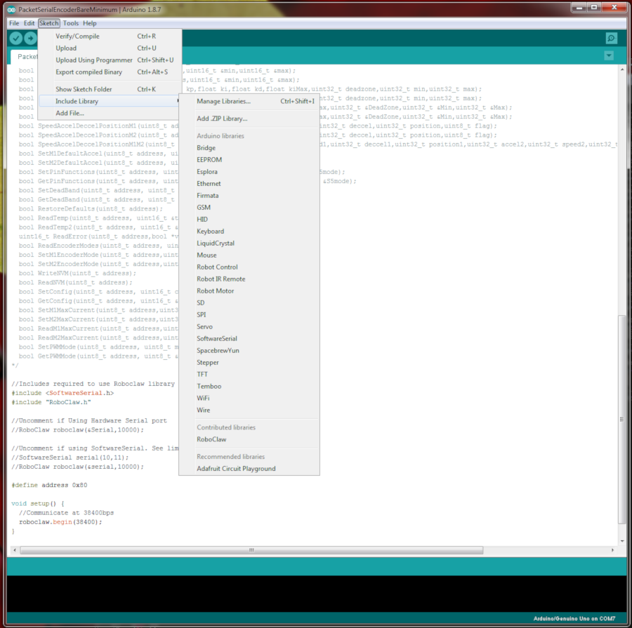
Figure 1: Adding the RoboClaw library to the Arduino IDE.
3. Power and one or two motors must be wired to the RoboClaw before beginning the process of wiring the A-Star and RoboClaw together. Motion Studio should also be used to verify that the controller and motor work properly before proceeding. Follow this tutorial to step 10 to do so.
4. See this tutorial on how to wire up a motor’s encoders to the RoboClaw.
5. Ensure that power to the RoboClaw and A-Star is disconnected before moving on to the next step.
6. A serial connection must be wired up between the A-Star and the RoboClaw boards. Three 0.1″ female to male jumper wires can be used to do so. Consult the table below for a list of the connections that must be made.
| Function | A-Star | RoboClaw |
| Receive | Pin 0 | S2 signal pin (pin closest to edge of board) |
| Transmit | Pin 1 | S1 signal pin (pin closest to edge of board) |
| Ground | Any ground pin | Any ground pin on the pin header |
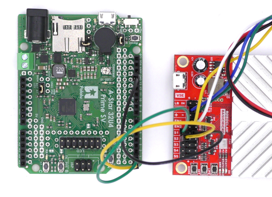
Figure 2: The serial port of the A-Star wired to the RoboClaw.
7. Connect the RoboClaw to the computer with a USB cable and reconnect power to the RoboClaw as done previously.
8. Open Basicmicro Motion Studio and connect the RoboClaw in use. Click on the left-hand pane titled “General Settings”. Find the area labeled “Setup” and set the Control Mode to Packet Serial. Now find the area labeled “Serial”. Set the field labeled Packet Serial Address to 128. Finally, in the same area, set the field titled Baudrate to 38400.
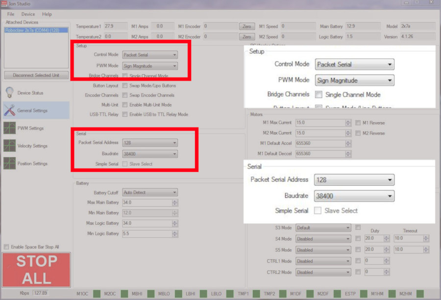
Figure 3: Setting the serial settings in Motion Studio.
9. Download the code for this tutorial from here or clone it from GitHub if Git is installed on the machine being used.
To clone the repository from GitHub run the following on the command line while in a folder or directory suitable for storing it.
git clone https://github.com/basicmicro/a_star_packet_serial.git
10. Connect the A-Star board to the computer with a USB cable. Note the port that it is using in the system’s device manager.
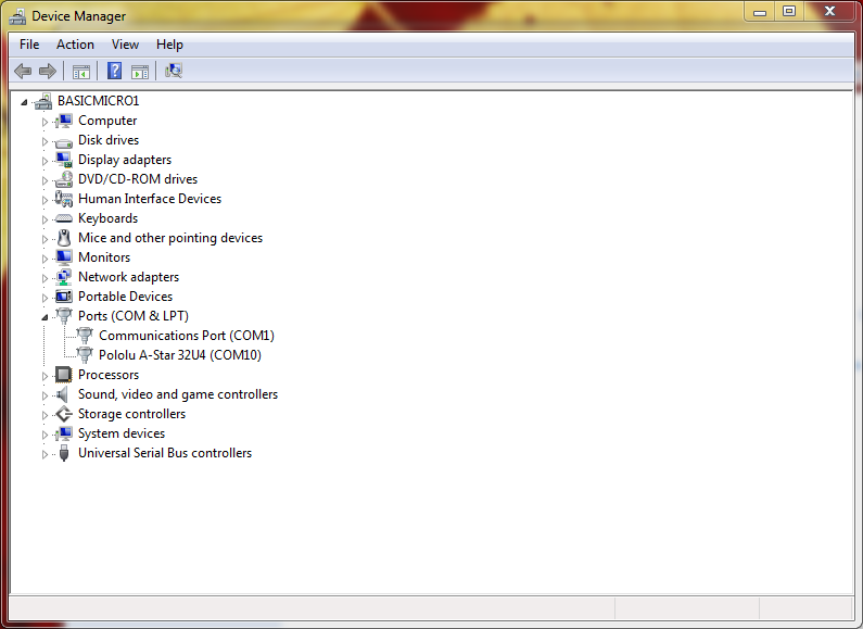
Figure 4: The device manager in Windows showing the A-Star com port.
11. Load the Arduino sketch up in the Arduino IDE. Set the board and port being used in the IDE. Once the code is open and the IDE is configured, upload the sketch to the board. The code will be compiled, loaded on to the board and begin running. If everything worked properly the motor attached to channel 1 of the RoboClaw will run in the forward direction at full speed for 2 seconds and then pause for two seconds before the process repeats.
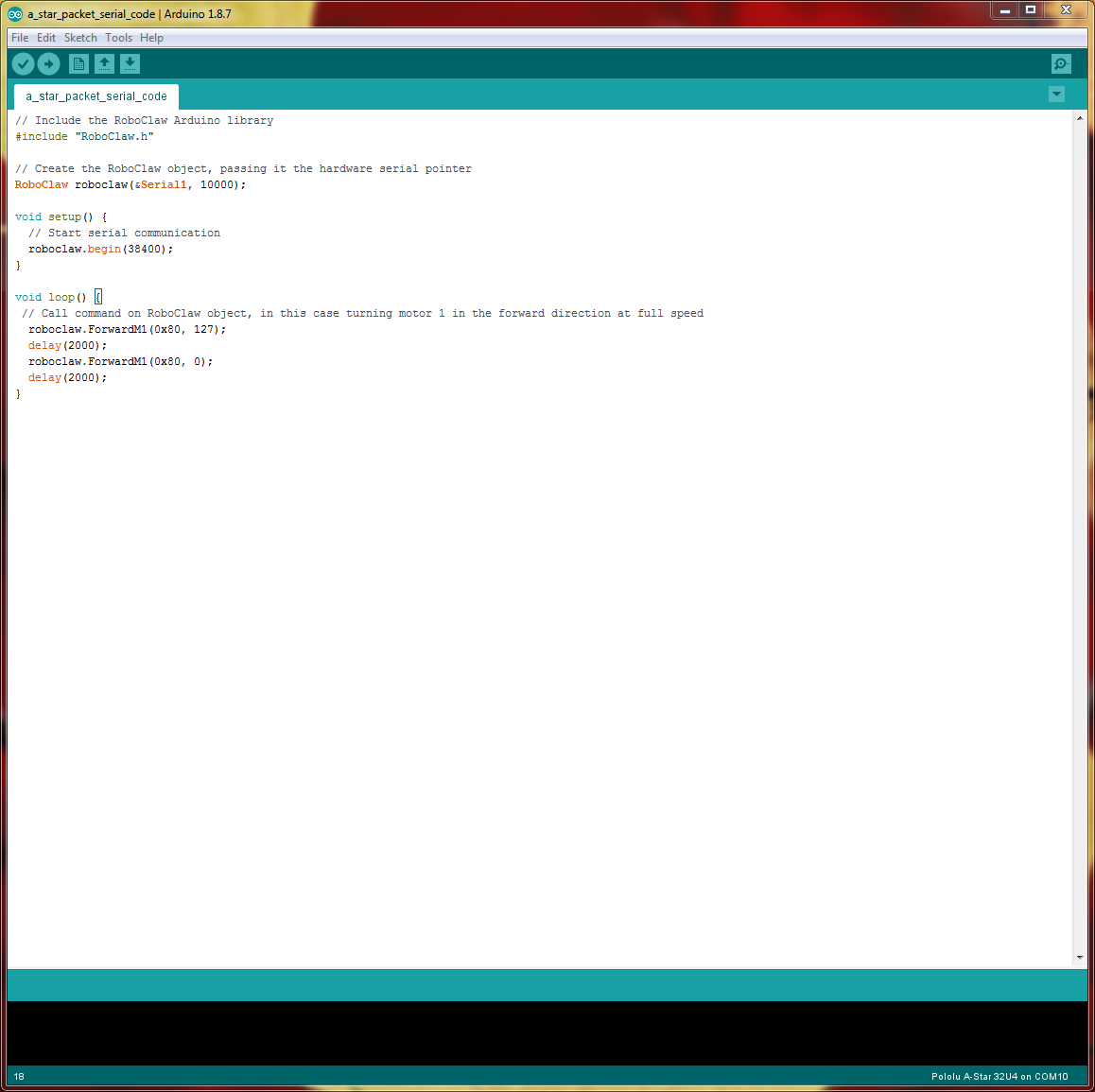
Figure 5: The sketch in the Ardino IDE.
Code Walkthrough
A walkthorugh of the code shows how simple and easy it is to control the RoboClaw from the A-Star:
The first line includes the RoboClaw library in the sketch.
#include “RoboClaw.h”
The next line creates the RoboClaw object. Note that two parameters are passed in to the constructor. The first is a pointer to the hardware serial object defined in the Arduino library. The second value is the serial communication timeout length in milliseconds.
RoboClaw roboclaw(&Serial1, 10000);
In the “setup()” function the “begin()” function of the RoboClaw object is called. The value passed to the function is the baudrate for serial communication. This must match the value that was set in Motion Studio. The function call start the serial communication between the A-Star board and the RoboClaw.
roboclaw.begin(38400);
In the loop function a RoboClaw command is carried out twice. The first call to “ForwardM1()” starts the motor as full speed and the second call stops the motor. The two values passed in to the function are the address of the RoboClaw, in this case 0x80, and the speed value which is 127 in the first call and 0 in the second call. Agter each command to the RoboClaw “delay()” is called to pause the program execution for two seconds.
roboclaw.ForwardM1(0x80, 127);
delay(2000);
roboclaw.ForwardM1(0x80, 0);
delay(2000);
delay(2000);
roboclaw.ForwardM1(0x80, 0);
delay(2000);
More commands that can be called on the RoboClaw object can be found in this Application Note. They are listed under the heading of “RoboClaw Library Functions”.
For a full listing of the commands in the RoboClaw Arduino library please read the library code that was downloaded earlier.