
The RoboClaw Case and Fan kit protects the RoboClaw 2x15A, 2x30A and 2x45A motor controllers from impacts, dirt, debris and moisture, while the integrated fan cools the board so it can sustain higher currents for longer. This guide covers the complete assembly, from installing the fan to closing up the case.
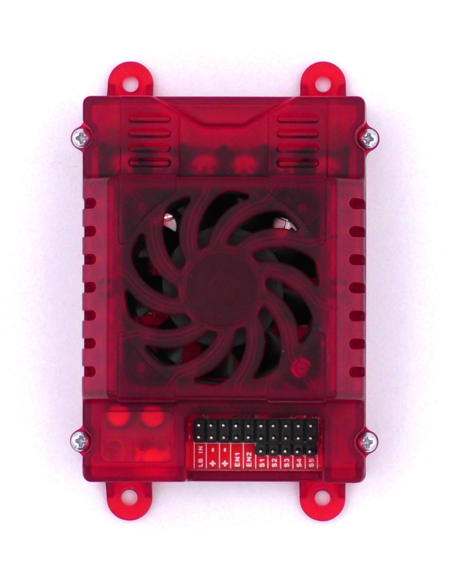
The RoboClaw Case and Fan is available directly from BasicMicro as well as from resellers. It fits the RoboClaw 2x15A, 2x30A and 2x45A motor controllers. The case does not fit the ST (screw terminal) models.
Why Use a Case?
A case offers several advantages over running a bare board. First, it prevents physical damage. In many robotics applications the motor controller can come into contact with objects that could damage exposed components. Second, some robots operate in environments where dirt, debris and moisture are present. The case keeps these contaminants off the board, some of which could otherwise cause a short circuit and permanent damage to the motor controller.
How the Fan Works
The integrated fan blows ambient air across the board, carrying heat away. A cooler board can operate at higher current values and can run at high current for extended periods of time. The RoboClaw firmware controls the fan automatically, turning it on at 45C and off at 35C. No configuration is required.
What You Need
- 1× RoboClaw Case and Fan
- 1× RoboClaw 2x15A, RoboClaw 2x30A or RoboClaw 2x45A motor controller
- 1× Phillips screwdriver
Assembling the Case and Fan
The following parts come included with the case:
- Case top
- Case bottom
- Fan
- Fan side plates
- Screws
- Stickers
- Install the fan in the top half of the case, using Figures 2 and 3 as a reference. Align the fan as shown in the photos, then secure it in place by installing the two side plates. Each side plate is held with a single screw.
Note the direction the label on the fan is facing. A fan installed backwards will cool the motor controller poorly.
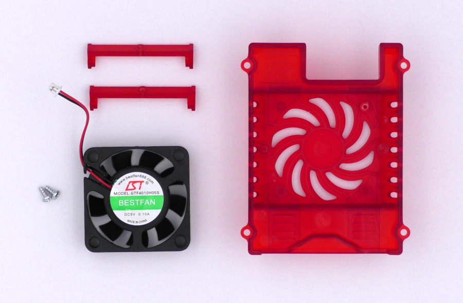
Figure 2: The parts needed to install the fan. 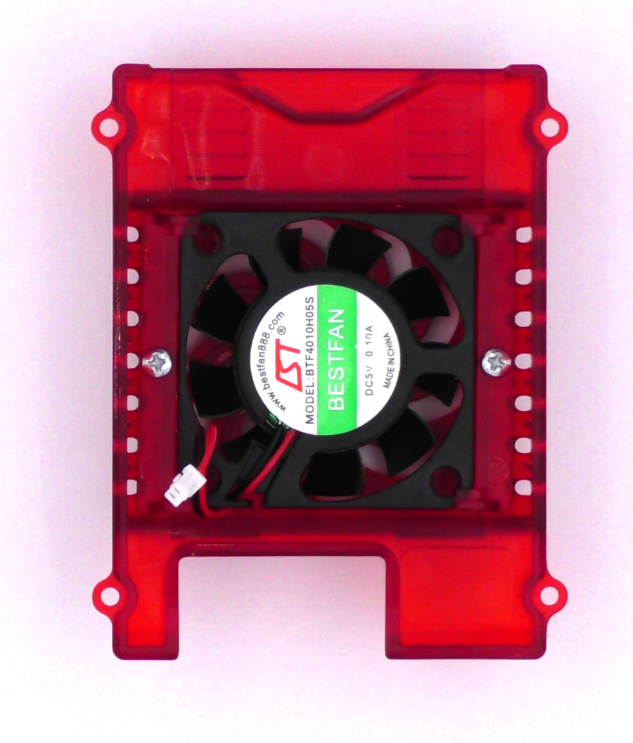
Figure 3: The fan after installation. - Place the motor controller in the bottom half of the case, orienting the board so the USB connector lines up with the opening for it in the case. Secure the board to the case with four screws.
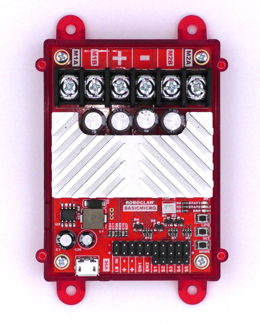
Figure 4: The motor controller installed in the bottom half of the case. - Connect the fan connector to the header labeled fan on the motor controller. The connector only goes in one way and should plug in easily and snugly. Do not force it.
Plugging the fan connector in backwards will damage the fan and the fan driver on the motor controller. Check the orientation of the connector before applying power.
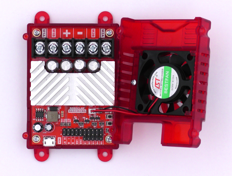
Figure 5: The fan connected to the header on the motor controller. - Place the top half of the case on the bottom half and secure the two halves with four screws.
Figure 6: The completed case assembly.
Next Steps
With the motor controller in its case, it is ready for wiring and configuration. RoboClaw Basics covers the fundamentals of setting up and using a RoboClaw, and Configuring RoboClaw Battery Settings walks through setting the voltage limits for your battery before the first run.


