
A RoboClaw motor controller can drive a linear actuator with analog position feedback as a closed loop servo. Wire the motor to channel 1, divide the feedback signal down to the 0 to 2 volt input range, set the encoder mode to Absolute, and tune the position PID in Motion Studio.
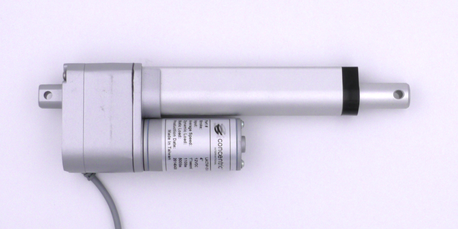
Linear actuators are commonly used in robotics projects and serve a variety of purposes. Models with a built-in feedback potentiometer report their extension as an analog voltage, which a RoboClaw motor controller can read as an absolute encoder for precise, repeatable position control. This Application Note covers how to connect a feedback linear actuator to a RoboClaw, condition its feedback signal, tune it for position control in BasicMicro Motion Studio, and command positions from an Arduino over packet serial.
What You Need
- (1) RoboClaw motor controller, such as the RoboClaw 2x7A or the RoboClaw Solo 30A
- (1) Linear actuator with position feedback
- (1) RoboClaw Screw Terminal Adapter (optional, dual channel models only)
- (1) Resistor (value varies, see the table below)
- (1) Capacitor (0.01 to 0.1 uF)
- (3) 0.1″ female crimp pins
- (3) 0.1″ female crimp connector housings
- (1) Crimper
- (1) Wire stripper
- (1) Soldering iron and solder
- (3) Pieces of heat shrink tubing
- (1) Multimeter
- (1) Computer with BasicMicro Motion Studio installed
- (1) Micro USB cable
- (1) Small screwdriver
- (1) Arduino Uno and jumper wires (optional, for the code example)
Why Does the Actuator Wiring Need Modification?
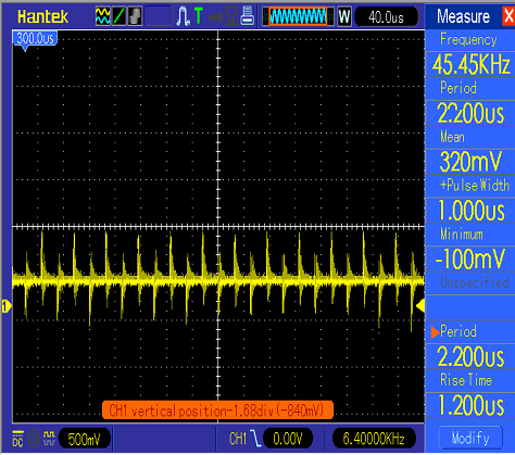
A problem with many linear actuators, including the one used in this guide, is that the wires for the motor’s power run close to or directly alongside the wires for the feedback system. When a PWM (pulse width modulated) power signal is sent to the motor, noise from the power wires couples onto the feedback wires and produces a noisy output signal. The motor controller then reads an erratic signal rather than a steady voltage, which makes it difficult or impossible to determine the exact position of the actuator. If the controller uses the noisy position data in a feedback loop, the actuator can operate erratically or not at all.
Signal Line Noise
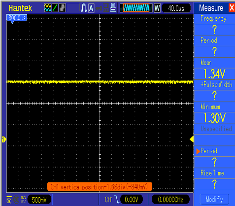
To solve the noise issue, a capacitor is added across the signal and ground lines of the feedback system. The capacitor smooths the signal into something much closer to a steady voltage. The capacitor must be sized appropriately or a delay can be introduced into the signal. When using a RoboClaw with an analog feedback output, a capacitor between 0.01 and 0.1 uF is recommended.
Feedback Voltage Range
The other consideration is the voltage range of the feedback signal. The RoboClaw reads absolute encoders with its internal analog to digital converter, which has an input range of 0 to 2 volts. The pins are 5 volt tolerant, but any signal above 2 volts reads as full scale. The encoder power pins on the RoboClaw supply 5 volts, so the potentiometer output must be divided down to stay within range.
This is done by adding a resistor in series with the potentiometer’s power lead, forming a voltage divider with the potentiometer itself. The resistor value is approximately 1.5 times the total resistance of the potentiometer, which brings the maximum feedback voltage down to 2 volts. To find the resistance of the potentiometer, use a multimeter to measure between the power and ground leads of the feedback wiring. Use the calculated value or the next larger standard resistor value; a slightly larger resistor keeps the signal safely under 2 volts at the cost of a small amount of range.
| Potentiometer Resistance | Resistor Value |
|---|---|
| 500 ohms | 750 ohms |
| 1k ohms | 1.5k ohms |
| 2k ohms | 3k ohms |
| 5k ohms | 7.5k ohms |
| 10k ohms | 15k ohms |
| 22k ohms | 33k ohms |
| 47k ohms | 70.5k ohms |
| 50k ohms | 75k ohms |
| 100k ohms | 150k ohms |
| 220k ohms | 330k ohms |
| 470k ohms | 705k ohms |
| 500k ohms | 750k ohms |
| 1M ohms | 1.5M ohms |
Preparing the Actuator Wiring
The actuator ships with connectors that do not fit the RoboClaw. Cutting them off and crimping 0.100″ connectors onto the feedback wires makes the actuator plug directly onto the RoboClaw’s pin headers.
- Cut off the supplied power connector and strip a small section of insulation from both power wires.
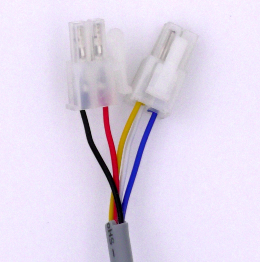
Figure 4: The original connectors for power and feedback. - Cut off the connector for the potentiometer wiring and strip the ends of all three potentiometer wires. Using the crimper, crimp a female pin onto each wire. Finally, slide a female connector housing onto each wire, aligning the hole in the housing with the tab on the pin.
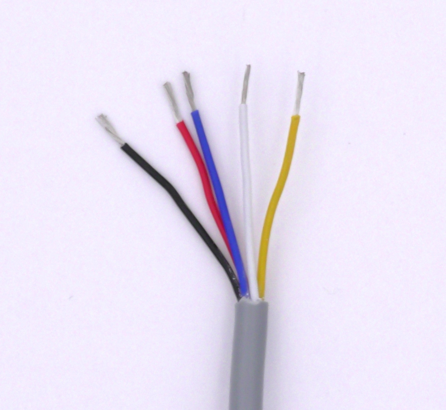
Figure 5: All connections cut and stripped. 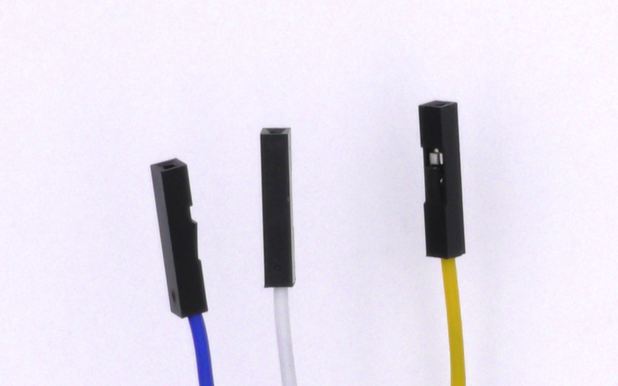
Figure 6: The connectors added to the ends of the wiring harness.
Optional: Using the RoboClaw Screw Terminal Adapter
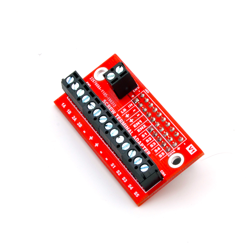
On dual channel RoboClaw models there is an alternative to crimping connectors. The RoboClaw Screw Terminal Adapter plugs onto the RoboClaw’s pin headers and routes all of the I/O to screw terminals, so the stripped feedback wires can be landed directly under screw terminals with no crimping. The adapter also works as a quick disconnect for the whole harness. It is compatible with the RoboClaw 7A, 15A, 30A, 45A, 60A and 60A HV dual channel models.
The RoboClaw Solo models do not have a screw terminal adapter available. When using a Solo, crimp the 0.100″ connectors as shown above.
Installing the Resistor and Capacitor
The resistor and capacitor are soldered directly into the feedback wiring. Each of the three potentiometer wires is cut at a midpoint, and the components are soldered in at the cuts, as shown in Figure 8.
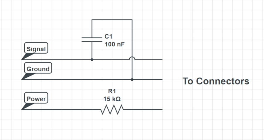
- Cut each of the three potentiometer wires (power, signal, and ground) at a midpoint and strip the cut ends.
- Solder the resistor from the table above into the power wire, joining its two cut ends through the resistor so it sits in series with the lead.
- Solder the signal wire and the ground wire back together, leaving a small area of exposed metal at each solder joint. Then solder one leg of the capacitor to each joint so the capacitor bridges the signal and ground lines.
- Place heat shrink over the exposed sections of each wire and heat it until it shrinks down over the soldered connections.
Connecting the Actuator to the RoboClaw
- Connect the actuator’s two power leads to motor channel 1. On dual channel models these are the M1A and M1B screw terminals. On the Solo they are the yellow and green motor wires.
- Connect the potentiometer leads to the RoboClaw’s pin headers using the table below as a reference. The pin functions are marked on the board.
| Function | Actuator Lead | Dual Channel RoboClaw | RoboClaw Solo |
|---|---|---|---|
| Power | Power lead (through the added resistor) | Encoder power header positive pin | +5V pin |
| Ground | Ground lead | Encoder power header ground pin | GND pin |
| Signal | Signal lead | EN1 A pin | 1A pin |
Configuring the RoboClaw in Motion Studio
- Power up the motor controller by connecting a power supply or battery.
- Connect the motor controller to a computer with a micro USB cable.
- Open Motion Studio and click “Connect Selected Unit” to connect the controller in the application.
- Navigate to the “General Settings” screen and find the pane labeled “Encoders” (1). Set “Encoder 1 Mode” (2) to “Absolute”.
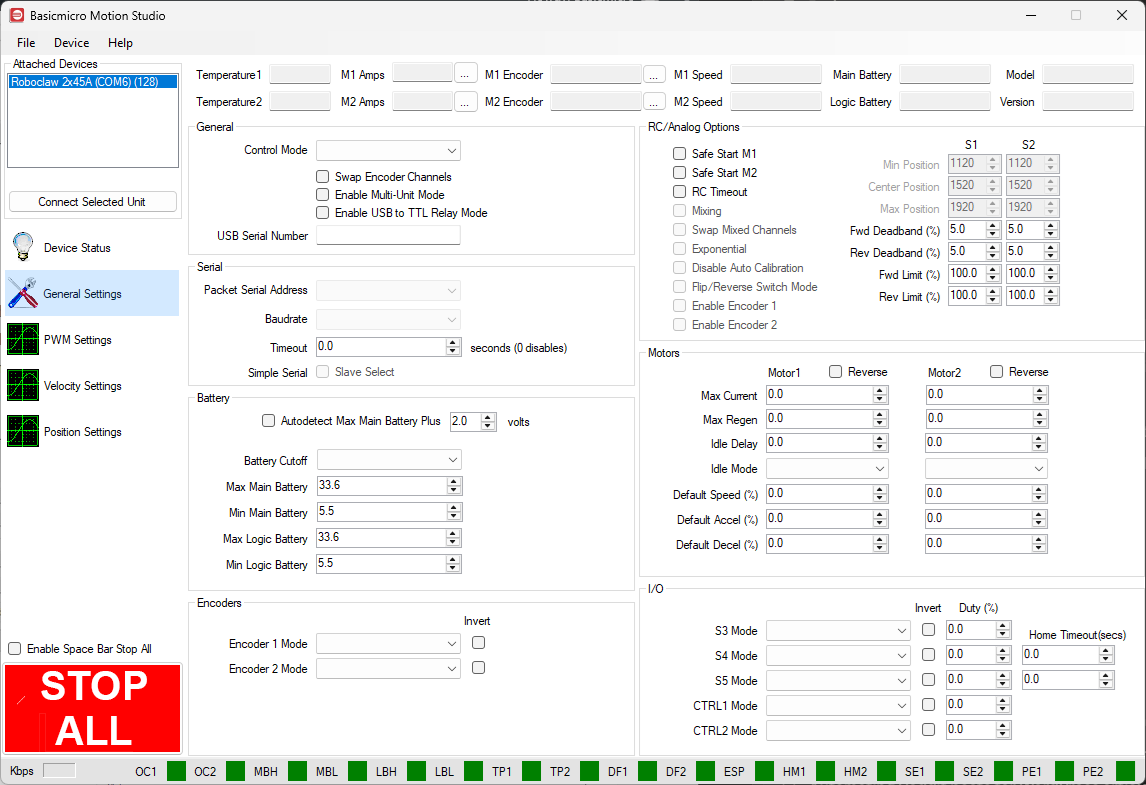
Figure 9: Location of the Encoders pane (1) and the Encoder 1 Mode setting (2) in General Settings.
Testing the Actuator
Check whether the actuator has built-in limit switches before driving it. The actuator used in this guide stops itself at both ends of travel, but many linear actuators do not. Without limit switches, driving the actuator into a mechanical end stop stalls the motor at full current, which can strip the actuator’s gearing or burn out the motor. On actuators without limit switches, approach the ends of travel slowly and stop before the hard stops.
- In the “PWM Settings” screen, use the slider for motor channel 1 to drive the actuator’s motor back and forth. If the motor does not move in the desired direction when moving the slider up, power down the controller and reverse the two motor connections on channel 1.
- Move the channel 1 slider up and note the direction the count changes in the “M1 Encoder” box at the top of the application. The count should increase as the actuator extends. If the count runs in the wrong direction, enable the “Invert” option on “Encoder 1 Mode” in General Settings.
Tuning for Position Control
The final step in setting up a linear actuator with a RoboClaw is tuning for position control. Position control allows the actuator’s extension to be set precisely and repeatably. The position PID parameters must be set and tuned before position control will work. Motion Studio includes an Auto Tune function, but with absolute encoders such as a feedback potentiometer, the limited resolution and higher susceptibility to noise can prevent reliable results, so manual tuning is recommended for linear actuators.
- In the “PWM Settings” screen, use the slider to run the actuator at full speed and note the value in the “M1 Speed” box at the top of the application. This is the maximum speed of the system in encoder counts per second.
- Still in “PWM Settings”, drive the actuator to its fully retracted and fully extended positions. At each end, note the value in the “M1 Encoder” box.
- In the “Velocity Settings” screen, set the velocity P, I and D values for motor 1 to 0. Simple position control does not use the velocity PID.
- Navigate to the “Position Settings” screen and find the pane labeled “Position Settings” (1). Enter the speed value found in step 15 in the box labeled “QPPS” (2).
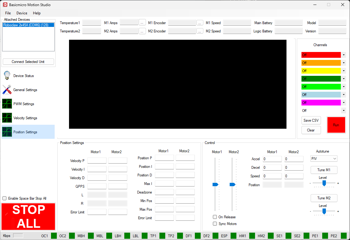
Figure 10: Location of the Position Settings pane (1), the QPPS field (2), and the position PID tuning fields (outlined).
- Locate the boxes labeled “Min Pos” and “Max Pos”. Enter values just inside the encoder readings recorded at each end of travel, leaving a safety margin before each physical stop so the actuator is never commanded into its dead stops.
- Enter a starting value of 2000 in the “Position P” box for motor 1, with I and D at 0. The position tuning fields are outlined in Figure 10. Test the movement with the position slider.
- Gradually increase P until the actuator overshoots its target when the slider is moved, then increase D while leaving I at 0. D acts as a damping force and is typically 5 to 20 times larger than P. Adjust P and D back and forth until the actuator moves smoothly and stops at the target without overshoot.
- If the actuator stops close to the target but not exactly on it, a small I value can be added. In systems with mechanical play, I can cause the actuator to hunt back and forth around the target; if this happens, increase the “Deadzone” value so the controller treats positions near the target as close enough.
- Save the tuned values to the controller by clicking “Write Settings” in the “Device” menu so they are reloaded at every power up.
Controlling the Actuator from an Arduino
Once the position PID is tuned, the actuator can be commanded from a microcontroller in packet serial mode. The example below runs on an Arduino Uno and takes commands from the Arduino IDE’s Serial Monitor: type a target position in encoder counts to move the actuator, or type r to read the current position. The sketch uses the Basicmicro Arduino library and communicates with the RoboClaw over software serial.
- In Motion Studio, open “General Settings” and set the “Control Mode” to “Packet Serial”. Leave the baud rate at 38400 and the address at 128, then save with “Write Settings” in the “Device” menu.
- Wire the Arduino to the RoboClaw’s pin headers: Arduino pin 11 to the S1 signal pin, Arduino pin 10 to the S2 signal pin, and Arduino GND to a RoboClaw GND pin.
- Install the Basicmicro Arduino library from the Arduino IDE’s Library Manager. The install procedure is covered in Using the RoboClaw Arduino Library.
This sketch uses two serial connections at once: the USB connection to the computer for the Serial Monitor, and a software serial connection to the RoboClaw. On an Uno this is unavoidable, because the board’s only hardware serial port is the USB connection, so a sketch that prints results must put the controller on software serial.
Update the constants at the top of the sketch with the values found during tuning: the speed measured in step 15 (or a lower cruise speed), and the minimum and maximum positions entered in step 19. Then upload the sketch to the Arduino.
#include <SoftwareSerial.h>
#include <Basicmicro.h>

#define ADDRESS 128

// Software serial to the RoboClaw: pin 10 to S2 (RoboClaw TX), pin 11 to S1 (RoboClaw RX)
SoftwareSerial controllerSerial(10, 11);
Basicmicro roboclaw(&controllerSerial, 10000);

// Replace these with the values found while tuning in Motion Studio
const uint32_t ACCEL   = 500;   // acceleration in counts per second per second
const uint32_t SPEED   = 400;   // cruise speed in counts per second, at or below the measured maximum
const uint32_t DECCEL  = 500;   // deceleration in counts per second per second
const long     MIN_POS = 100;   // minimum position entered in Motion Studio
const long     MAX_POS = 1900;  // maximum position entered in Motion Studio

void setup() {
  Serial.begin(57600);
  controllerSerial.begin(38400);
  Serial.println("Linear actuator terminal control");
  Serial.println("Enter a target position in encoder counts, or r to read the current position.");
}

void loop() {
  if (Serial.available()) {
    String input = Serial.readStringUntil('\n');
    input.trim();
    if (input.length() == 0) {
      return;
    }

    if (input == "r" || input == "R") {
      uint32_t position = roboclaw.ReadEncM1(ADDRESS);
      Serial.print("Current position: ");
      Serial.println(position);
      return;
    }

    long target = input.toInt();
    if (target < MIN_POS) {
      target = MIN_POS;
    }
    if (target > MAX_POS) {
      target = MAX_POS;
    }

    Serial.print("Moving to ");
    Serial.println(target);
    roboclaw.SpeedAccelDeccelPositionM1(ADDRESS, ACCEL, SPEED, DECCEL, target, 1);
  }
}
Open the Serial Monitor at 57600 baud with the line ending set to “Newline”. Typing a number sends the actuator to that position in encoder counts, clamped to the tuned minimum and maximum, using the SpeedAccelDeccelPositionM1() command so the move follows a controlled acceleration and deceleration profile. Typing r reads the current position with ReadEncM1().
Next Steps
For more on installing the library and the full set of motor control functions, see Using the RoboClaw Arduino Library. If the system runs from a power supply rather than a battery, set up regenerative energy protection as covered in Using a Voltage Clamp with RoboClaw. The full range of controllers for projects like this can be found on the RoboClaw motor controllers category page.


