Introduction
When in packet serial mode the RoboClaw offers a wide range of commands to control it’s full feature set. Any microcontoller of computer capable of serial communications can be used with this mode. In this App Note a Raspberry Pi is used together with the Python library available on the BasicMicro website. Four RoboClaws are used to demonstrate using packet serial in Multi-Unit Mode.
Materials
(4) RoboClaw motor controllers
(4) batteries, one for each RoboClaw
(15) female to female jumper wires
(4) motors, one for each RoboClaw
(1) Raspberry Pi 3
(1) power supply and micro USB cable for Raspberry Pi
(1) keyboard, mouse and monitor for the Raspberry Pi
(1) internet connection for Raspberry Pi
(1) micro USB cable for the RoboClaw
(1) soldering iron
(1) solder
(1) computer with BasicMicro Motion Studio installed
(1) small screwdriver
Let’s get started
1. Wire one motor and battery to each RoboClaw. Follow this tutorial to step to 10.
2. Follow this tutorial to configure the Raspberry Pi’s serial port.
3. Remove power from all RoboClaws if not done previously.
4. Shutdown the Raspberry Pi.
5. Cut and strip the ends off of five female to female 0.1″ jumper wires. Strip and tin the ends of all five wires. Solder the tinned ends of 4 of the wires together producing a bundle of 4 wires. Finally solder the end of the fifth wire to the bundle so that the connector is on the opposite side of the other connectors. Repeat this process two more times, producing three wiring harnesses. One will be used for the transmit line, another for the receive line and finally one for the ground connections.
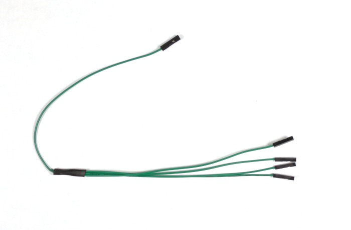
Figure 1: An example of a completed wiring harness. Three of these are needed.
6. Wire the Raspbbery Pi and the RoboClaws together according to the table below. A pinout diagram of the Raspberry Pi’s GPIO header can be found here.
| Function | Raspberry Pi | RoboClaw |
| Transmit | GPIO 14 | S1 signal pin on each |
| Recieve | GPIO 15 | S2 signal pin on each |
| Ground | Any ground pin | S1 ground pin on each |
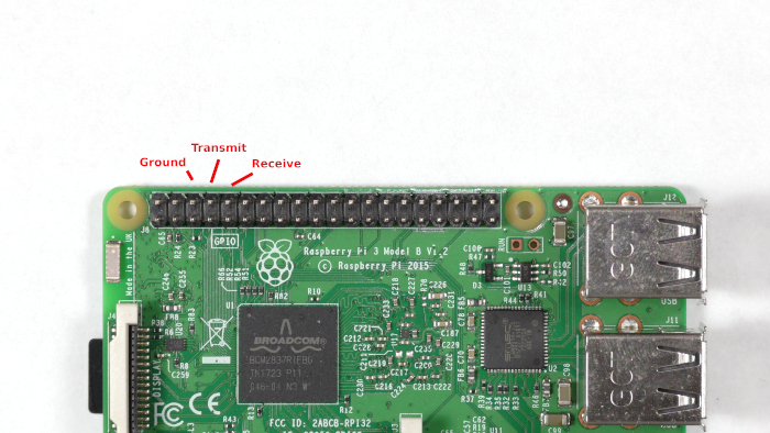
Figure 2: GPIO pins that are used for this App Note.
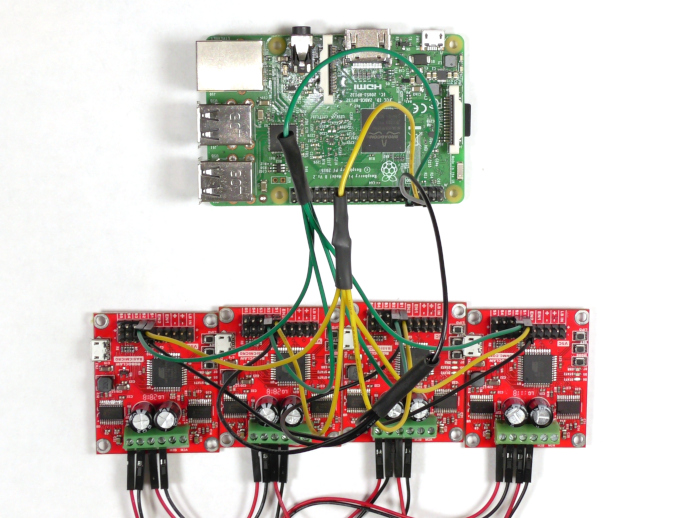
Figure 3: The Raspberry Pi and 4 RoboClaws wired together.
7. Power up all of the attched RoboClaws.
8. Connect on the RoboClaws to the computer with a micro USB cable and open Motion Studio. Connect the attached RoboClaw in Motion Studio as done in the tutorial linked in step one. On the left-hand side of the application click on “General Settings”. Find the pane labeled “Setup”. The the “Control Mode” to “Packet Serial” and check the box for “Enable Multi-Unit Mode”. Now find the pane labeled “Serial”. Set the “Packet Serial Address” of the RoboClaw to 128 and set the baudrate to 38400. Repeat this process for each of the other RoboClaws setting their addresses to 129, 130, and 131 respectively.
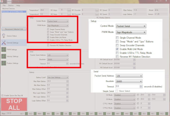
Figure 4: Settings for packet serial bus operation.
9. Turn the Raspberry Pi back up by reconnecting power to it.
10. Ensure that the Raspberry Pi has an internet connection.
11. Next add the pyserial library to the Pi’s Python library. Open a terminal and enter the following command:
If pip is not installed on the Raspberry Pi it can be installed with the following commmand:
12. Dowload the test code for this tutorial from here.
The repository can also be cloned from GitHub from the commandline. Install Git with the following command:
Then clone the repository with the following command:
13. Unzip the code you’ve downloaded and navigate to the unzipped directory via the terminal. If you’ve cloned the repository with Git there is nothing to unzip. Run the code provided by entering the following:
14. The code is packet_serial_bus.py starts by creating a list of addresses of the attached RoboClaws. In then creates an instance of the RoboClaw class with the settings for the serial port as parameters to the constructor. The serial port is then opened by calling ‘roboclaw.Open()’. An infinite loop is started and the list of address if cycled through. For each address in the list of addresses the RoboClaw runs the motor in the forward direction for two seconds and is then stopped.
15. One by one each motor should run for two seconds and then stop. If this behavior is not observed there are a few things to check. First verify that the trasmit and receive lines are not reversed. Next make sure that there is a solid ground connection between the Raspberry Pi and each RoboClaw board. Finally reconnect each RoboClaw to Motion Studio and verify that the control mode is set to “Packet Serial”, “Multi-Unit mode” is enabled, the baudrate set to 38400 and that each RoboClaw has a unique address as detailed in the code.