Introduction
The Raspberry Pi feaures a 40 pin GPIO header that can be used to control external hardware and a serial port for communciation with external hardware. In this Application Note a Raspberry Pi will be used to control 4 RoboClaw motor controllers in standard serial mode. The serial port is used to send single byte commands and 4 GPIO pins are used to select which RoboClaw is active at any given time.
Materials
(4) RoboClaw motor controllers
(4) batteries, one for each RoboClaw
(14) female to female jumper wires
(4) motors, one for each RoboClaw
(1) Raspberry Pi 3
(1) power supply and micro USB cable for Raspberry Pi
(1) keyboard, mouse and monitor for the Raspberry Pi
(1) internet connection for Raspberry Pi
(1) micro USB cable for the RoboClaw
(1) soldering iron
(1) solder
(1) computer with BasicMicro Motion Studio installed
(1) small screwdriver
Let’s get started
1. Wire one motor and battery to each RoboClaw. Follow this tutorial to step to 10.
2. Follow this tutorial to configure the Raspberry Pi’s serial port.
3. Remove power from all the RoboClaws if not done previously.
4. Shutdown the Raspberry Pi.
3. Cut and strip the ends off of five female to female 0.1″ jumper wires. Strip and tin the ends of all five wires. Solder the tinned ends of 4 of the wires together producing a bundle of 4 wires. Finally solder the end of the fifth wire to the bundle so that the connector is on the opposite side of the other connectors. Repeat this process to make another harness.
Photo of harness 1
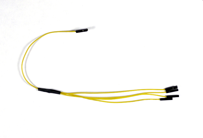
Figure 1: Transmit wiring harness.

Figure 2: Ground wiring harness.
4. Wire the RoboClaws and Raspberry Pi according to the table below. A pinout diagram of the Raspberry Pi’s GPIO header can be found here.
| Function | Raspberry Pi | RoboClaw |
| Transmit | GPIO 14 | S1 signal pin on each |
| Ground | Any ground pin | S1 ground pin on each |
| Slave Select | GPIO 23 | S2 signal pin of first controller |
| Slave Select | GPIO 24 | S2 signal pin of second controller |
| Slave Select | GPIO 25 | S2 signal pin of third controller |
| Slave Select | GPIO 8 | S2 signal pin of fourth controller |
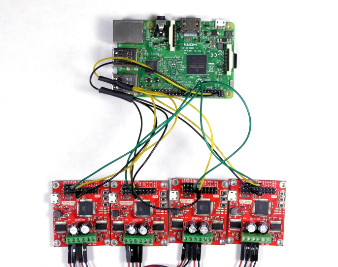
Figure 3: RoboClaws and Raspberry Pi wired together.
5. Apply power to all of the RoboClaws.
6. Connect a RoboClaw to a computer with Motion Studio installed with a micro USB cable. Open Motion Studio and connect the listed motor controller as done in the tutorial linked to in step 1. On the left-hand side of the application click on ‘General Settings’. Locate the pane labeled “Setup” and set “Control Mode” to “Simple Serial”. Next move down to the pane labeled “Serial”. Set “Baudrate” to 38400 and check the box labeled “Slave Select”. To save the settings to the board click on “Device” in the menu at the top of the window and then click “Write Settings”. Disconnect the RoboClaw by clicking “Disconnect Selected Unit”. Repeat this process for each RoboClaw in use.
Photo of settings in Motion Studio
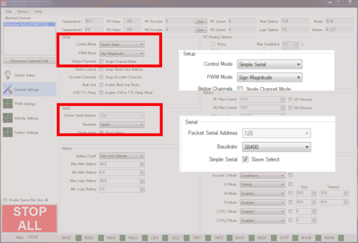
Figure 4: Standard serial bus settings in Motion Studio.
7. Turn on the Raspberry Pi by reconnecting power to it via the micro USB connection.
8. Ensure that the Raspberry Pi has an internet connection.
9. Next add the pyserial library to the Pi’s Python library. Open a terminal and enter the following command:
If pip is not installed on the Raspberry Pi it can be installed with the following commmand:
10. Install the RPi.GPIO library by entering the following command:
11. Dowload the test code for this tutorial from here.
The repository can also be cloned from GitHub from the commandline. Install Git with the following command:
Then clone the repository with the following command:
12. Unzip the code you’ve downloaded and navigate to the unzipped directory via the terminal. If you’ve cloned the repository with Git there is nothing to unzip. Run the code provided by entering the following:
13. At this point the motors should be running one at a time in the order the controllers are wired to the Raspberry Pi’s GPIO headers. Each motor should run for 2 seconds followed by a pause of two seconds before the next motor starts running. If you encounter problems first check to see if the connections at S1 and S2 are wired in the proper sequence. Next check to ensure there is a solid ground connection between the Raspberry Pi and each RoboClaw. Finally check to see if the individual motors are wired properly to channel 1 of their respective RoboClaw.