Introduction
The Raspberry Pi 3 is a popular single board computer with the ability to interface to external hardware via the onboard GPIO pins. This Application Note cover how to use the serial port of the Raspberry Pi to control a RoboClaw in standard serial mode.
Materials
(1) RoboClaw motor controller
(2) motors for RoboClaw
(1) battery for RoboClaw
(1) Raspberry Pi 3 or 3B+
(3) female to female jumper cables
(1) small screwdriver
(1) computer with BasicMicro Motion Studio installed
(1) micro USB cable for the RoboClaw
(1) power source for Raspberry Pi
(1) monitor, mouse and keyboard for the Raspberry Pi
(1) HDMI cable for Raspberry Pi
Let’s get started
1. Follow this tutorial to step 10 to prepare the RoboClaw.
2. Follow this tutorial to configure the serial port hardware on the Raspberry Pi.
3. Disconnect power from the RoboClaw if this hasn’t been done already.
4. Shutdown the Raspberry Pi.
5. Wire the Raspberry Pi and the RoboClaw together according to the table below.
| Raspberry Pi | RoboClaw |
| GPIO 14 | S1 signal pin (pin closest to board edge) |
| Any ground pin | S1 ground pin (pin closest to inside of board) |
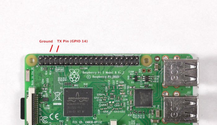
Figure 1: Pins to wire on the Raspberry Pi.
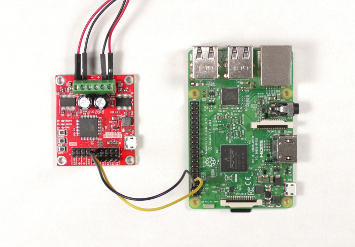
Figure 2: The Raspberry Pi and RoboClaw wired together.
6. Reconnect power to the RoboClaw.
7. Connect the RoboClaw to the computer with a micro USB cable. Open BasicMicro Motion Studio and connect the RoboClaw as done previuosly in the tutorial linked in step 1.
8. In the Motion Studio application click on “General Settings” in the left-hand pane. Now locate the pane titled “Setup”. Set the control mode to “Simple Serial”. Now move down to the pane labeled “Serial”. Set the baudrate to 38400. Disconnect the RoboClaw by clicking “Disconnect Selected Unit” in the upper left-hand side of Motion Studio.
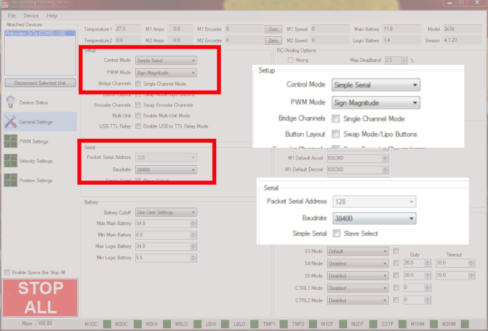
Figure 3: Serial configuration in Motion Studio.
9. Power up the Raspberry Pi by connecting power to it with the micro USB cable.
10. Ensure that the Raspberry Pi has access to an internet connection, either via wireless or a wired connection.
11. Next add the pyserial library to the Pi’s Python library. Open a terminal window and enter the following command:
12. Dowload the test code for this tutorial from here.
13. Unzip the code you’ve downloaded and navigate to the unzipped directory via the terminal. Run the code provided by entering the following:
14. The motors should now be running according to the code in the test program. Motor 1 should rotate in the forwards direction for 2 seconds, stop for 2 seconds and then run backwards for 2 seconds. The process then repeats for the second motor.
Additional Notes
If the motors are not running as expected ensure that the connections between the Pi and the RoboClaw are secure. Also make sure that the TX line is connected correctly. The TX from the Pi (GPIO 14) goes to the RX pin on the RoboClaw (S1 signal pin). Finally check to see if there is a solid common ground connection between the two boards.
In the code provided single byte commands are sent to control the two motors. The speed and direction of both motors can be controlled with these single byte commands in standard serial mode. The table below is an explantion of how to use these commands for control of one or both motors.
| Value | Function |
| 0 | Shuts down channels 1 and 2 |
| 1 | Channel 1 full reverse |
| 64 | Channel 1 stop |
| 127 | Channel 1 full forward |
| 128 | Channel 2 full reverse |
| 192 | Channel 2 stop |
| 255 | Channel 2 full forward |