
An ESP32 can control a RoboClaw motor controller over packet serial using the Basicmicro Arduino library and one of its hardware UARTs. Wire two GPIO pins and ground to the RoboClaw’s S1 and S2 headers, install the ESP32 board package and the Basicmicro library, and flash one of the complete example sketches below.
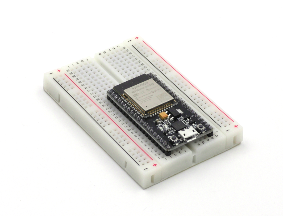
The ESP32 is a family of inexpensive WiFi and Bluetooth microcontroller boards with multiple hardware serial ports, which makes it a natural fit for controlling a RoboClaw motor controller in packet serial mode. The microcontroller can run standalone control logic for the RoboClaw, or the WiFi radio can be used to control a project remotely from any device with a browser. This article covers wiring an ESP32 to a RoboClaw, setting up the Arduino IDE, and two complete sketches: a minimal packet serial demo and a WiFi web interface that drives both motor channels and displays live telemetry. Everything here works on both classic ESP32 boards and the newer ESP32-S3 variants.
What You Need
- 1× RoboClaw motor controller
- 2× Brushed DC motors
- 1× Battery or power supply for the RoboClaw
- 1× ESP32 development board, classic or S3
- 1× Breadboard
- 3× Female-to-male jumper wires
- 1× USB cable for the ESP32 board
- 1× Computer with Motion Studio and the Arduino IDE installed
How Do You Wire the ESP32 to the RoboClaw?
- Wire the motors and a power source to the RoboClaw. The Dual Channel RoboClaw Quick Start Guide covers motor and battery wiring in detail.
- If the motors have encoders, wire them following Pololu Encoder Wiring. The web interface sketch displays encoder counts and speeds, but both examples run fine without encoders.
- Connect the RoboClaw to Motion Studio over USB and set its control mode to Packet Serial. Note the address and baud rate configured there; the sketches in this article use the defaults, address 0x80 and 38400 baud.
Motion Studio is a free download from the BasicMicro downloads page, and Installing BasicMicro Motion Studio covers the install.
- Place the ESP32 board in the breadboard so jumper connections can be made to its pins.
- Connect three jumper wires between the ESP32 and the RoboClaw: GPIO 17 to the signal pin of the RoboClaw’s S1 header, GPIO 16 to the signal pin of the S2 header, and a ground pin on the ESP32 to a ground pin on either header. S1 is the RoboClaw’s receive side and S2 is its transmit side, so the ESP32’s transmit pin (GPIO 17) goes to S1 and its receive pin (GPIO 16) goes to S2.
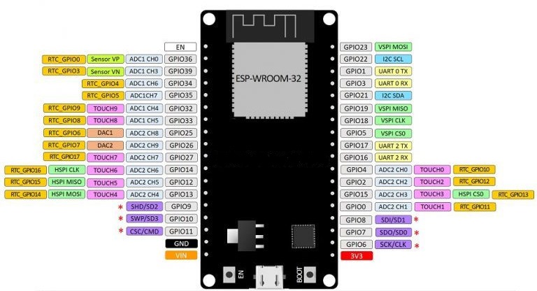
Figure 2: The GPIO ports of the ESP32 board used in this article. 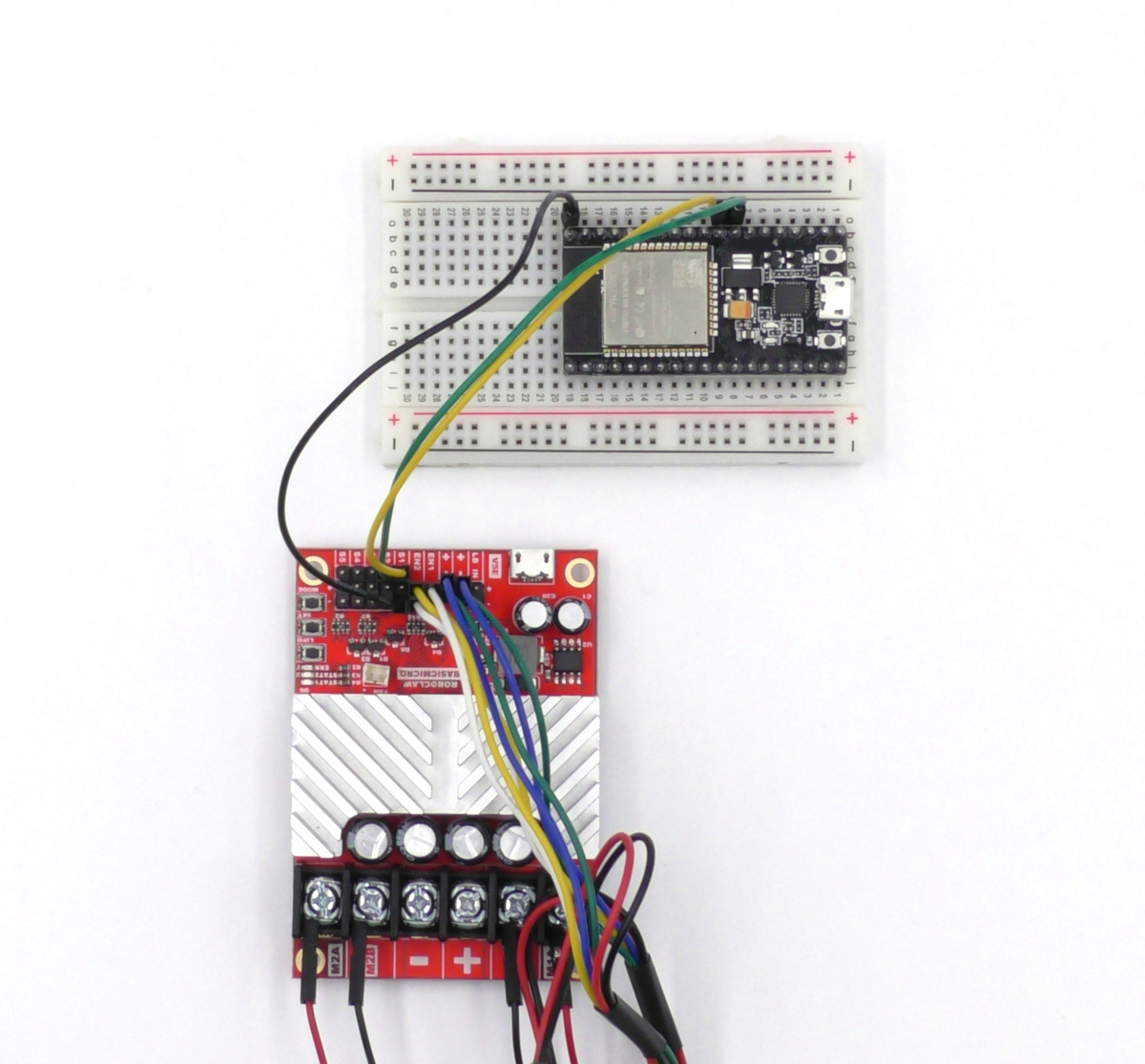
Figure 3: The serial ports of the RoboClaw and ESP32 wired together.
How Do You Set Up the Arduino IDE for the ESP32?
- Open the Arduino IDE preferences (File > Preferences) and add the ESP32 boards manager URL below to the “Additional boards manager URLs” field, separating it from any existing entries with a comma, then click OK.
https://espressif.github.io/arduino-esp32/package_esp32_index.json - Open Tools > Board > Boards Manager, search for “esp32”, and install the “esp32 by Espressif Systems” package. The download and install take a few minutes.
- Install the Basicmicro Arduino library: in the Arduino IDE, go to Sketch > Include Library > Manage Libraries, search for “Basicmicro”, and click Install. Using the RoboClaw Arduino Library covers the library itself in detail.
- Connect the ESP32 board to the computer with a USB cable. This powers the board as well as programs it.
- Select the board under Tools > Board in the ESP32 Arduino section. Classic development boards are typically “ESP32 Dev Module” (the NodeMCU-style board pictured above is “Node32s”), and S3 boards are “ESP32S3 Dev Module”. Then select the board’s port under Tools > Port; on Windows, Device Manager lists it under Ports (COM & LPT).
- To flash a sketch, click the Upload button with the right-facing arrow above the code editor. On some boards the BOOT button must be held while the upload starts, and some need the EN or reset button pressed to run the newly flashed code; check the documentation for the board being used.
The sketches below work without modification on both classic ESP32 and ESP32-S3 boards: they map the serial port to GPIO 16 and 17 explicitly, and both pins are free on standard WROOM-style classic boards and S3 development boards. Just select the matching board in the IDE. Two exceptions: classic boards built on a WROVER module use GPIO 16 and 17 for PSRAM, and re-pinning on an S3 should avoid GPIO 19 and 20, its USB pins. On those boards, choose two free pins, wire them to the RoboClaw instead, and update RXPIN and TXPIN at the top of the sketch.
Running the Packet Serial Demo
The sketch below is the smallest complete example: it runs motor channel 1 and then channel 2 forward at about 50% duty cycle for two seconds each, stopping between. Older versions of the ESP32 Arduino core mapped Serial2 to GPIO 16 and 17 automatically; current versions define no default pins for it, so the sketch maps the pins explicitly in Serial2.begin(). That explicit mapping is also what lets the same code run unchanged on S3 boards.
// Runs both RoboClaw motor channels in sequence over packet serial.
// Works on classic ESP32 and ESP32-S3 boards.

#include <Basicmicro.h>

// UART pins wired to the RoboClaw (TXPIN to S1, RXPIN to S2)
#define RXPIN 16
#define TXPIN 17

// Address and baud rate as set in Motion Studio
#define ADDRESS 0x80
#define BAUD 38400

Basicmicro controller(&Serial2, 10000);

void setup() {
  // Map Serial2 to the wired pins, then start the library on them
  Serial2.begin(BAUD, SERIAL_8N1, RXPIN, TXPIN);
  controller.begin(BAUD);
}

void loop() {
  // Run motor 1 forward at about 50% duty cycle, then stop it
  controller.DutyM1(ADDRESS, 16384);
  delay(2000);
  controller.DutyM1(ADDRESS, 0);
  delay(2000);

  // Run motor 2 forward at about 50% duty cycle, then stop it
  controller.DutyM2(ADDRESS, 16384);
  delay(2000);
  controller.DutyM2(ADDRESS, 0);
  delay(2000);
}
Flash the sketch and both motors should take turns running. If nothing moves, confirm the control mode, address, and baud rate in Motion Studio match the values at the top of the sketch, and that the TX and RX wires are not swapped.
Running the WiFi Web Interface
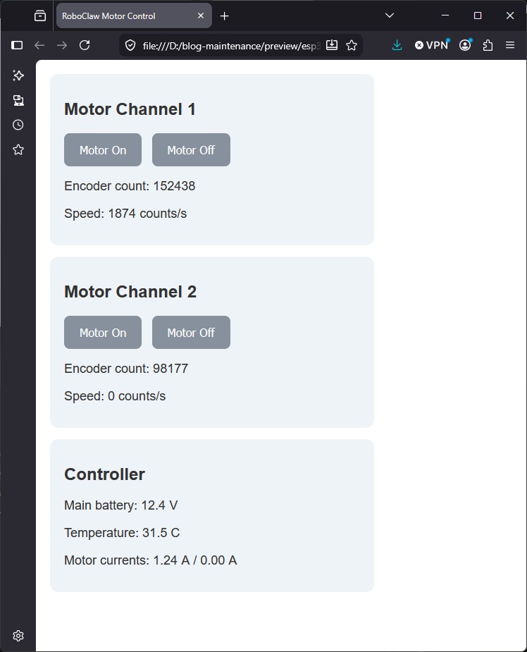
The second sketch turns the ESP32 into a WiFi access point serving a control page for the RoboClaw. Any device with WiFi and a browser can drive both motor channels and watch live telemetry: encoder counts, measured speeds, main battery voltage, board temperature, and both motor currents. All of the telemetry comes from a single GetStatus call per update, one packet serial command that returns every value the page displays. Using Encoders with the Arduino Library covers GetStatus in detail.
// WiFi web interface for RoboClaw motor control from an ESP32.
// The ESP32 runs as an access point; the served page drives both
// motor channels and shows live telemetry from GetStatus.
// Works on classic ESP32 and ESP32-S3 boards.

#include <WiFi.h>
#include <WebServer.h>
#include <Basicmicro.h>

// UART pins wired to the RoboClaw (TXPIN to S1, RXPIN to S2)
#define RXPIN 16
#define TXPIN 17

// Address and baud rate as set in Motion Studio
#define ADDRESS 0x80
#define BAUD 38400

// WiFi access point credentials
const char* AP_NAME = "esp32";
const char* AP_PASSWORD = "basicmicro";

Basicmicro controller(&Serial2, 10000);
WebServer server(80);

const char HOME_PAGE[] = R"=====(
<!DOCTYPE html>
<html>
<head>
<meta name="viewport" content="width=device-width, initial-scale=1">
<title>RoboClaw Motor Control</title>
<style>
  body { font-family: sans-serif; color: #333; margin: 20px; }
  .panel { background: #eef3f8; border-radius: 12px;
           padding: 16px 20px; margin-bottom: 16px; max-width: 420px; }
  button { font-size: 16px; padding: 14px 22px; margin-right: 10px;
           border: none; border-radius: 8px;
           background: #87919e; color: #fff; }
  p { font-size: 18px; }
</style>
</head>
<body>
<div class="panel">
  <h2>Motor Channel 1</h2>
  <button onclick="setMotor(1, 1)">Motor On</button>
  <button onclick="setMotor(1, 0)">Motor Off</button>
  <p>Encoder count: <span id="enc1">0</span></p>
  <p>Speed: <span id="speed1">0</span> counts/s</p>
</div>
<div class="panel">
  <h2>Motor Channel 2</h2>
  <button onclick="setMotor(2, 1)">Motor On</button>
  <button onclick="setMotor(2, 0)">Motor Off</button>
  <p>Encoder count: <span id="enc2">0</span></p>
  <p>Speed: <span id="speed2">0</span> counts/s</p>
</div>
<div class="panel">
  <h2>Controller</h2>
  <p>Main battery: <span id="voltage">0</span> V</p>
  <p>Temperature: <span id="temp">0</span> C</p>
  <p>Motor currents: <span id="current1">0</span> A /
     <span id="current2">0</span> A</p>
</div>
<script>
  function setMotor(channel, state) {
    fetch("/motor?channel=" + channel + "&state=" + state);
  }
  function updateStatus() {
    fetch("/status")
      .then(response => response.json())
      .then(data => {
        document.getElementById("enc1").textContent = data.enc1;
        document.getElementById("enc2").textContent = data.enc2;
        document.getElementById("speed1").textContent = data.speed1;
        document.getElementById("speed2").textContent = data.speed2;
        document.getElementById("voltage").textContent = data.voltage;
        document.getElementById("temp").textContent = data.temp;
        document.getElementById("current1").textContent = data.current1;
        document.getElementById("current2").textContent = data.current2;
      });
  }
  setInterval(updateStatus, 500);
</script>
</body>
</html>
)=====";

void handleHome() {
  server.send(200, "text/html", HOME_PAGE);
}

void handleMotor() {
  int channel = server.arg("channel").toInt();
  int state = server.arg("state").toInt();

  // About 50% duty cycle when on, 0 to stop
  uint16_t duty = (state == 1) ? 16384 : 0;

  if (channel == 1) {
    controller.DutyM1(ADDRESS, duty);
  } else if (channel == 2) {
    controller.DutyM2(ADDRESS, duty);
  }
  server.send(200, "text/plain", "ok");
}

void handleStatus() {
  uint32_t tick, state, enc1, enc2, speed1, speed2, ispeed1, ispeed2;
  uint16_t temp1, temp2, mainBatt, logicBatt;
  int16_t pwm1, pwm2, current1, current2;
  uint16_t speedError1, speedError2, posError1, posError2;

  // One GetStatus call returns every value the page displays
  bool ok = controller.GetStatus(ADDRESS, tick, state, temp1, temp2,
                                 mainBatt, logicBatt, pwm1, pwm2,
                                 current1, current2, enc1, enc2,
                                 speed1, speed2, ispeed1, ispeed2,
                                 speedError1, speedError2,
                                 posError1, posError2);
  if (!ok) {
    server.send(500, "application/json", "{}");
    return;
  }

  // Battery is in tenths of a volt, temperature in tenths of a
  // degree C, currents in hundredths of an amp. The measured motor
  // speeds are the ispeed values. The format string is a raw string
  // literal, like the page above, so the JSON quotes need no escaping.
  char json[240];
  snprintf(json, sizeof(json),
    R"({"enc1":%ld,"enc2":%ld,"speed1":%ld,"speed2":%ld,)"
    R"("voltage":%.1f,"temp":%.1f,"current1":%.2f,"current2":%.2f})",
    (long)(int32_t)enc1, (long)(int32_t)enc2,
    (long)(int32_t)ispeed1, (long)(int32_t)ispeed2,
    mainBatt / 10.0, temp1 / 10.0,
    current1 / 100.0, current2 / 100.0);
  server.send(200, "application/json", json);
}

void setup() {
  // Map Serial2 to the wired pins, then start the library on them
  Serial2.begin(BAUD, SERIAL_8N1, RXPIN, TXPIN);
  controller.begin(BAUD);

  // Start the WiFi access point and register the page handlers
  WiFi.softAP(AP_NAME, AP_PASSWORD);
  server.on("/", handleHome);
  server.on("/motor", handleMotor);
  server.on("/status", handleStatus);
  server.begin();
}

void loop() {
  server.handleClient();
  delay(1);
}
Flash the sketch, then connect a phone or computer to the WiFi network named “esp32” using the password “basicmicro”. Open a browser and go to 192.168.4.1: the control page loads, the Motor On and Motor Off buttons drive each channel, and the telemetry updates twice a second.
How Does the Web Interface Code Work?
The sketch has three parts. First, WiFi.softAP() starts the ESP32 as its own access point, so no router or existing network is needed, and a WebServer object routes incoming requests: the root path serves the control page, /motor handles button presses, and /status serves telemetry.
The control page itself is plain HTML and JavaScript stored in the sketch as a raw string. Its buttons call /motor with a channel and state, which the handler turns into a DutyM1() or DutyM2() command at about 50% duty cycle. A timer on the page fetches /status every half second and writes the returned values into the page.
The /status handler is where GetStatus earns its place: instead of separate packet serial reads for each encoder, speed, temperature, voltage, and current, one command returns all of them, and the handler formats the values it displays into a small JSON object with snprintf. Fewer serial transactions per update means less traffic on the bus and a quicker page.
Next Steps
The web interface is a starting point: the same pattern extends to speed and position commands, more telemetry, or a different control page. Using the RoboClaw Arduino Library is the full reference for the library’s functions, and Using Encoders with the Arduino Library covers reading encoders and GetStatus in depth.


