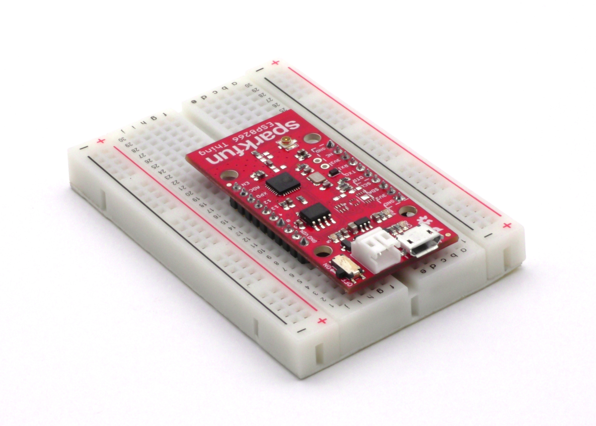
Figure 1: The Sparkfun ESP8266 Thing inserted in a breadboard.
Introduction
The Sparkfun ESP8266 Thing is Sparkfun’s version of the ESP8266 wifi enabled microcontroller board. Since the ESP8266 platform is Arduino compatible BasicMicro’s Arduino library for the RoboClaw motor controller can be used with it. This application note walks through setting up an ESP8266 Thing to talk to a RoboClaw motor controller and also provides some example code to test the functionality of the combination.
Materials
(1) RoboClaw motor controller
(1) power source for the RoboClaw
(1) Sparkfun ESP8266 Thing
(1) USB to serial adapter with DTR line
(2) motors with or without encoders
(3) 0.1″ jumper cables
(1) breadboard
(1) 0.1″ header pins
(1) soldering iron
(1) solder
(1) micro usb cable
(1) computer with Arduino IDE and Motion Studio installed
Let’s Get Started
1. Follow this tutorial to step 10 to attach both motors and power to the RoboClaw.
2. Complete steps 14-16 of this tutorial to configure the packet serial mode of the RoboClaw.
3. Before using the ESP8266 Thing for the first time and loading code on to the board the ESP8266 library must be added to the Arduino IDE. Begin by opening the Arduino IDE, select “File” and then “Preferences” in the menu at the top of the IDE. In the text box labeled “Board Manager URLs” add the URL below. Be sure to add a comma between entries if any other URLS are in the text box. Click “OK” when done.
http://arduino.esp8266.com/stable/package_esp8266com_index.json
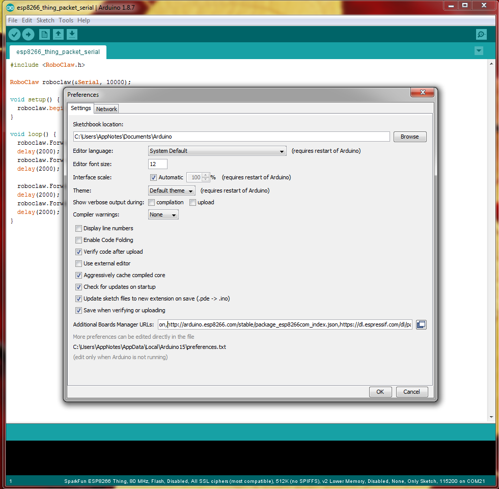
Figure 2: The location in the Arduino IDE to enter the board file URL.
Next, navigate to “Tools” > “Board” > “Board Manager” in the menu at the top of the IDE. Search for “ESP8266” and install the library. It will take several minutes for the library to be downloaded and installed.
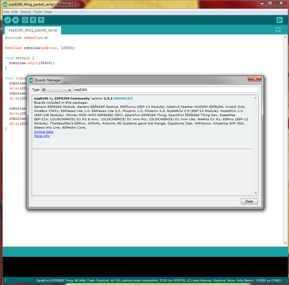
Figure 3: The board manager screen in the Arduino IDE.
4. The Thing board comes without header pins installed and cannot be inserted in a breadboard without them. Cut two lengths of header pins to match the number of holes on each side of the breadboard. Insert the pins in the breadboard with the proper spacing and then place the Thing board on the upper side of the pins. Solder each header pin to the Thing board.
5. Place the board pin side down in to a breadboard making sure there is room on either side of the board to make connections to the breadboard. Make sure the Thing board is well seated in the breadboard.
6. Connect the USB to serial adapter to the Thing board. Be sure that the adapter’s logic and power output is 3.3 volts, a 5 volt adapter will damage the Thing board. The following connections but me made: TX, RX, ground, DTR and 3.3V. Connect the USB side of the adapter to a computer.
7. In the Arduino IDE the Thing board must be selected and port for the USB to serial adapter must be set. First click on “Tools” and navigate the section labeled “Board”. Under the ESP8266 section select “Sparkfun ESP8266 Thing”.
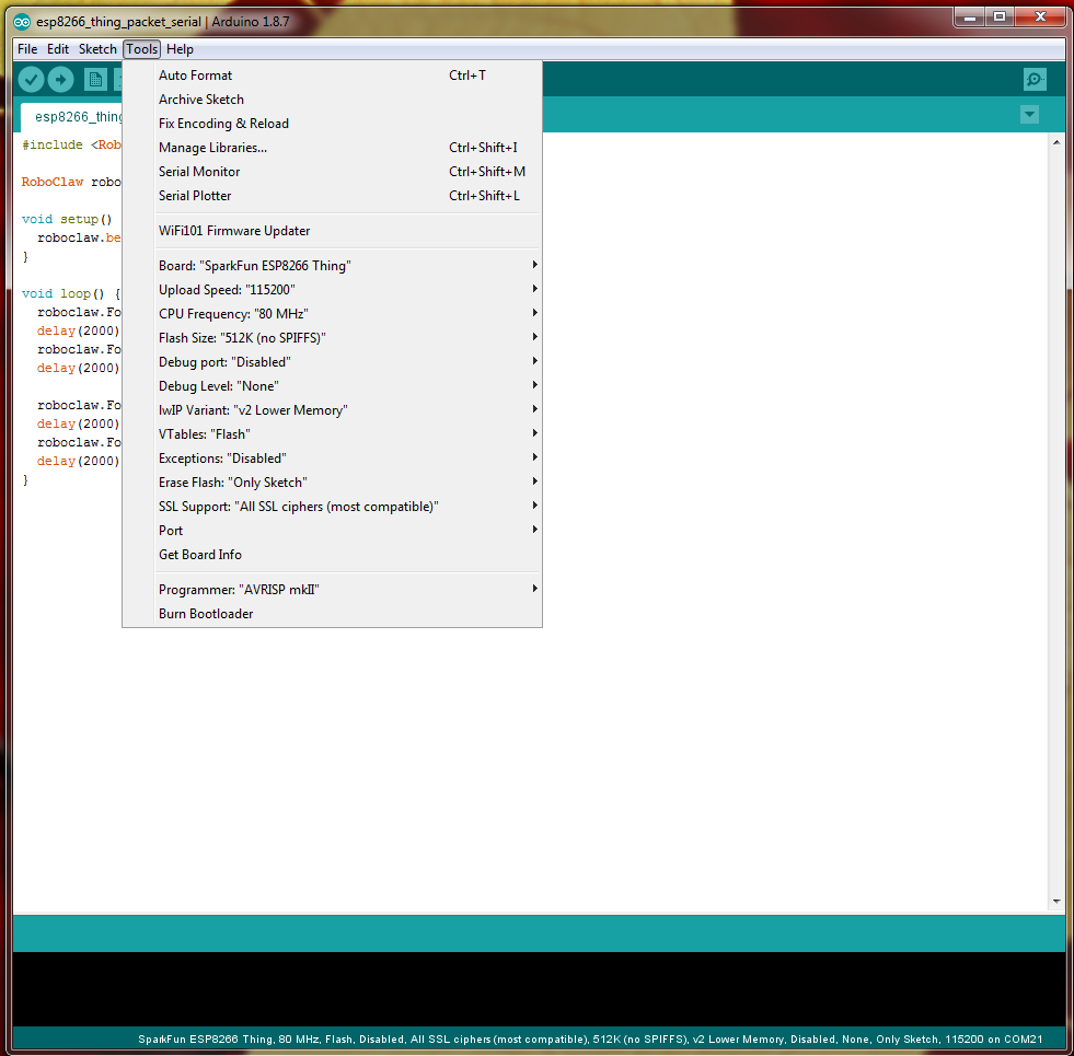
Figure 4: Location in the Arduino IDE to set the board in use.
Next set the port selection to the port that is associated with the USB to serial device being used. On a Windows based computer the Hardware Manager can be checked to determin the proper port setting.
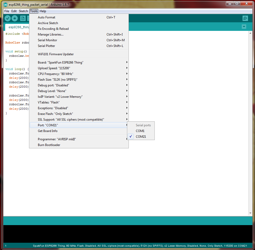
Figure 5: Location in the Arduino IDE to set the serial port for the programmer.
8. Download or clone the code for this Application Note from the Github repository.
9. From the downloaded code select which example file to flash. One example is a simple demo of packet serial communication to turn motors on and off with no usage of the wireless functionality of the Thing. The second example also controls both motors but features a web interface to control both motor channels. Open the file to flash to the Thing in the Arduino IDE. At the top of the IDE is a right-hand facing arrow button. Click this button and the code will be compiled and then uploaded to the board.
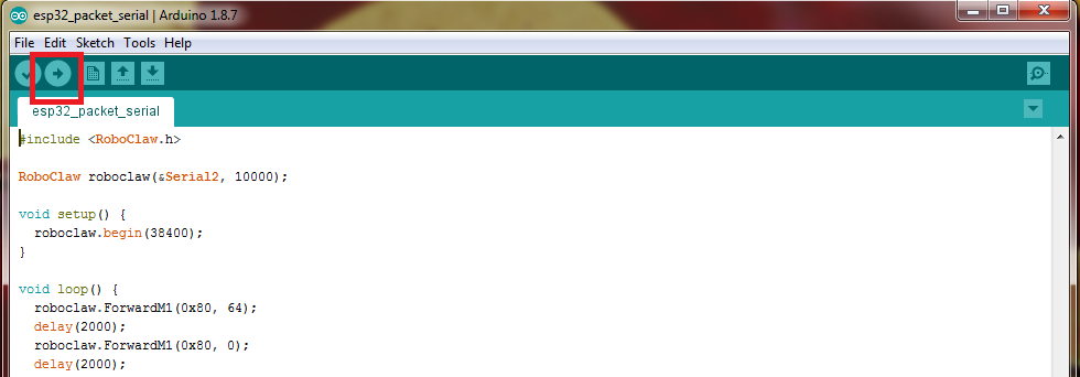
Figure 6: The button in the Arduino IDE to compile and upload code to the Thing board.
10. Disconnect the USB to serial adapter from the Thing and from the computer.
11. Using 3 jumper cables connect the RoboClaw to the Thing board. Connect the TX pin of the Thing to the signal pin of the RoboClaw’s S1 header. Connect the RX pin of the Thing to the RoboClaw’s S2 signal pin. Finally, connect the Thing’s serial ground pin to the ground pin of the S1 header on the RoboClaw.
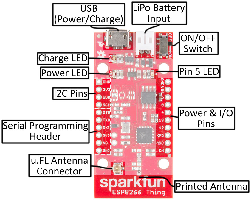
Figure 7: The Thing’s pinout.
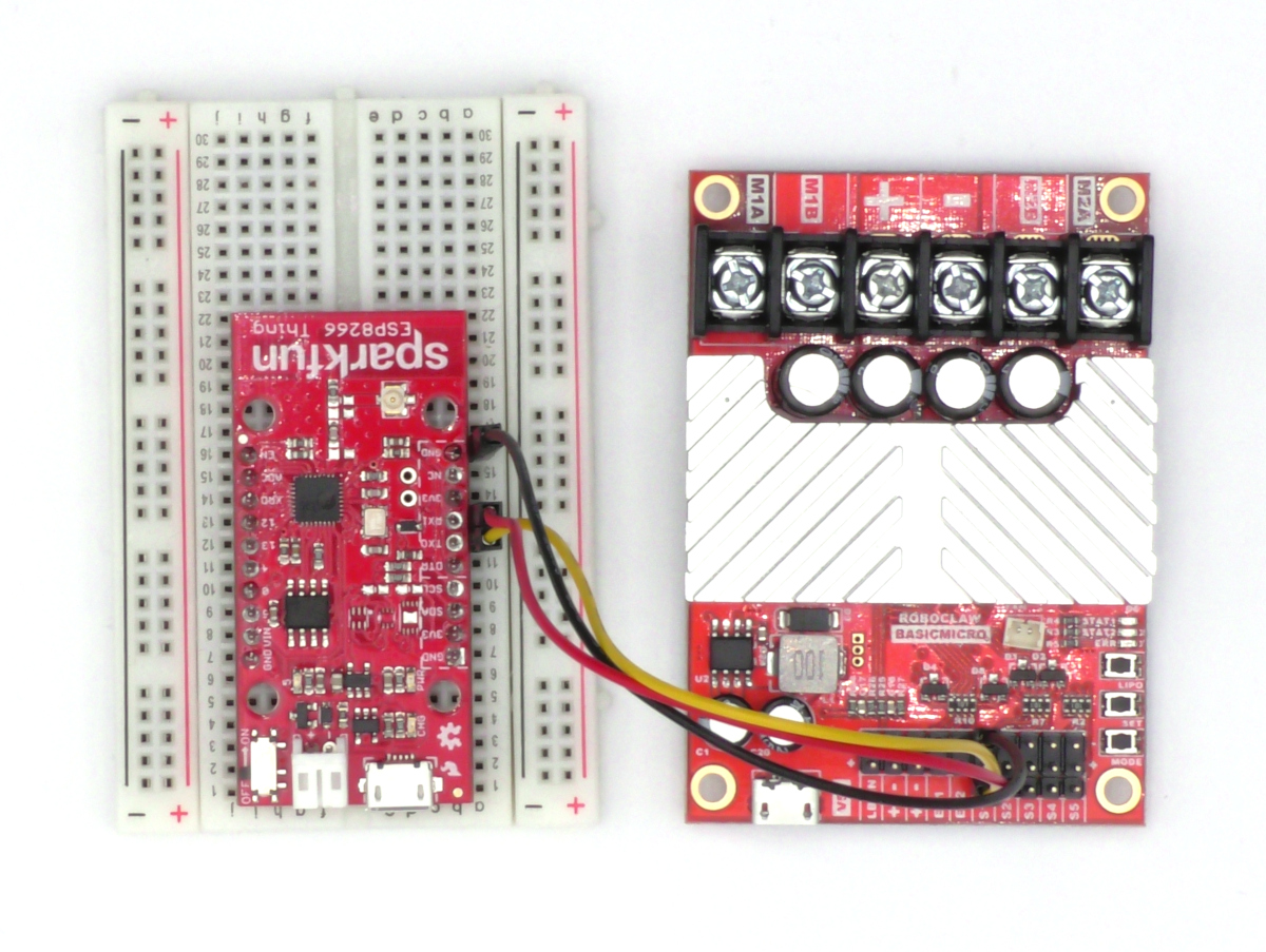
Figure 8: The serial ports of the RoboClaw and Thing wired together.
12. Reconnect power to the RoboClaw and read the section below for details about each code example.
Example Code
Packet Serial Test
The first example code uses the RoboClaw Arduino library to control the motor controller in packet serial mode. Once the RobClaw is powered on each motor channel will turn on for two seconds and then off for two seconds sequentially.
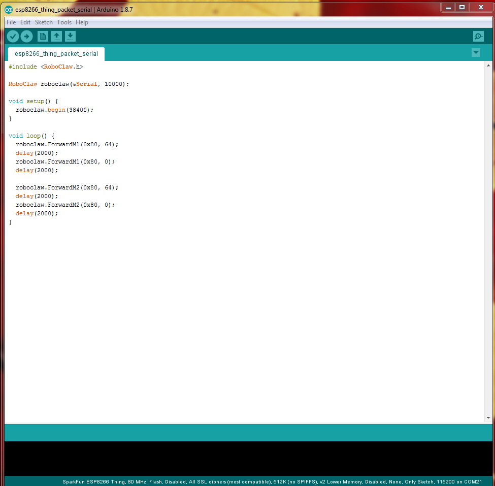
Figure 9: A packet serial example code in the Arduino IDE.
Motor Control Web Interface
The second example code provided uses the wifi functionality of the the esp8266 thing to create an access point and host a webpage that demonstrates controlling both motor channels wirelessly. As in the previous example the packet serial mode of RoboClaw is used with the Arduino library. To access the web page on the Thing connect to the access point named “esp8266_thing_test” and enter the password “basicmicro” when prompted. Open a web browser and enter the address “192.168.4.1” in the address bar. The web interface should be visible and can be used to turn both motor channels on and off.
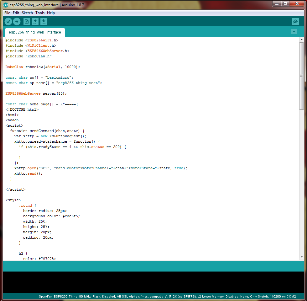
Figure 10: The web interface motor control example in the Arduino IDE.