Introduction
This Application Note builds on the
previous esp8266 article by incorporating AJAX requests and reporting data about the motor controller as well as attached encoders. The instructions for this App Note are similar to those of the previous article except for the additional step of attaching encoders to the motor controllers. Also the code for this App Note is substantially different from that of the last one. Read the code itself as well as the walk trough at the end of this App Note for an understanding of how everything fits together.
Figure 1: A close up view of the esp8266 board.
Materials
(1) RoboClaw motor controller
(2) DC brushed motors with quadrature encoders
(1) power supply for RoboClaw
(1) NodeMCU esp8266 1.0 board
(1) breadboard
(3) 0.1″ female to male jumper cables
(1) micro USB cable
(1) computer with Motion Studio and Arduino IDE installed
(1) small screwdriver
Let’s Get Started
1. Follow
this Application Note to step 10 to wire the RoboClaw’s power and motor connections.
2. Follow
this Application Note to step 7 to wire and verify the operation of the motor’s encoders.
3. Turn the RoboClaw on by connecting power to it.
4. Connect the RoboClaw to a computer with a micro USB cable. Open Motion Studio and connect the RoboClaw by clicking “Connect Selected Unit”. Click on “General Settings” on the left-hand side of the application. Locate the pane labeled “Setup” and set the dropdown label “Control Mode” to Packet Serial. Next locate the pane labeled “Serial”. Set the “Packet Serial Address” to 128 and set the drop down labeled “Baudrate” to 38400.
Save the settings to the board by opening the menu option labeled “Device” at the top of the application and clicking “Write Settings”. Finally click “Disconnect Selected Unit” to disconnect the RoboClaw.
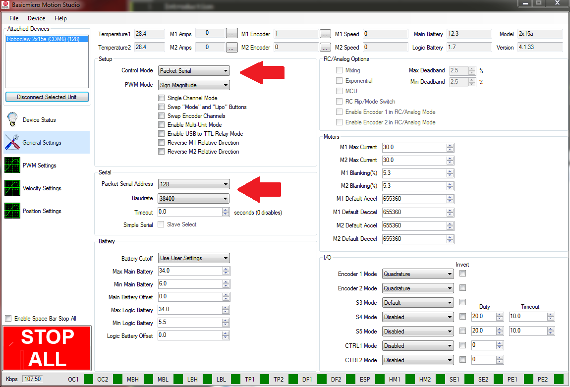
Figure 2: The mode and serial setting in Motion Studio.
5. Turn the RoboClaw off by disconnecting it’s power supply.
6. Place the esp8266 board in the breadboard leaving room on either side for connections.
7. Wire the RoboClaw and the esp8266 board together with jumper wires according to the table below. There is also a photo below of the two boards wired together.
|
Function |
esp8266 |
RoboClaw |
|
Ground |
Ground pin |
S1 ground pin |
|
Transmit |
GPIO15 |
S1 signal pin |
|
Receive |
GPIO 13 |
S2 signal pin |
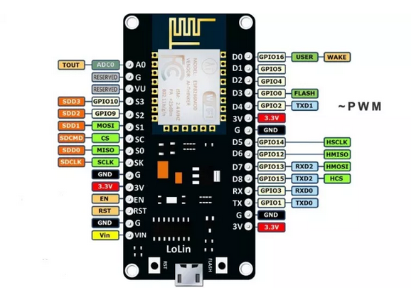
Figure 3: The pinout of the NodeMCU esp8266 board.
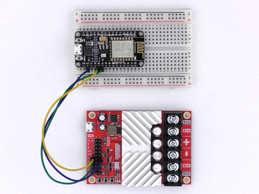
Figure 4: The RoboClaw and esp8266 wired together.
8. Install the esp8266 board software and libraries by following
this documentation.
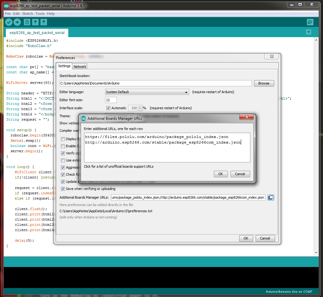
Figure 5: The Arduino IDE board manager.
9. Follow the section labeled “Adding the RoboClaw library to the Arduino IDE” in
this app note to install the RoboClaw library.
10. Connect the esp8266 board to a computer with a micro USB cable. Using the computer’s system tools determine what serial port the board is on. In the Arduino IDE open the “Tools” menu and set the esp8266 board in use and the port. The board used in this app note is the NodeMCU 1.0.
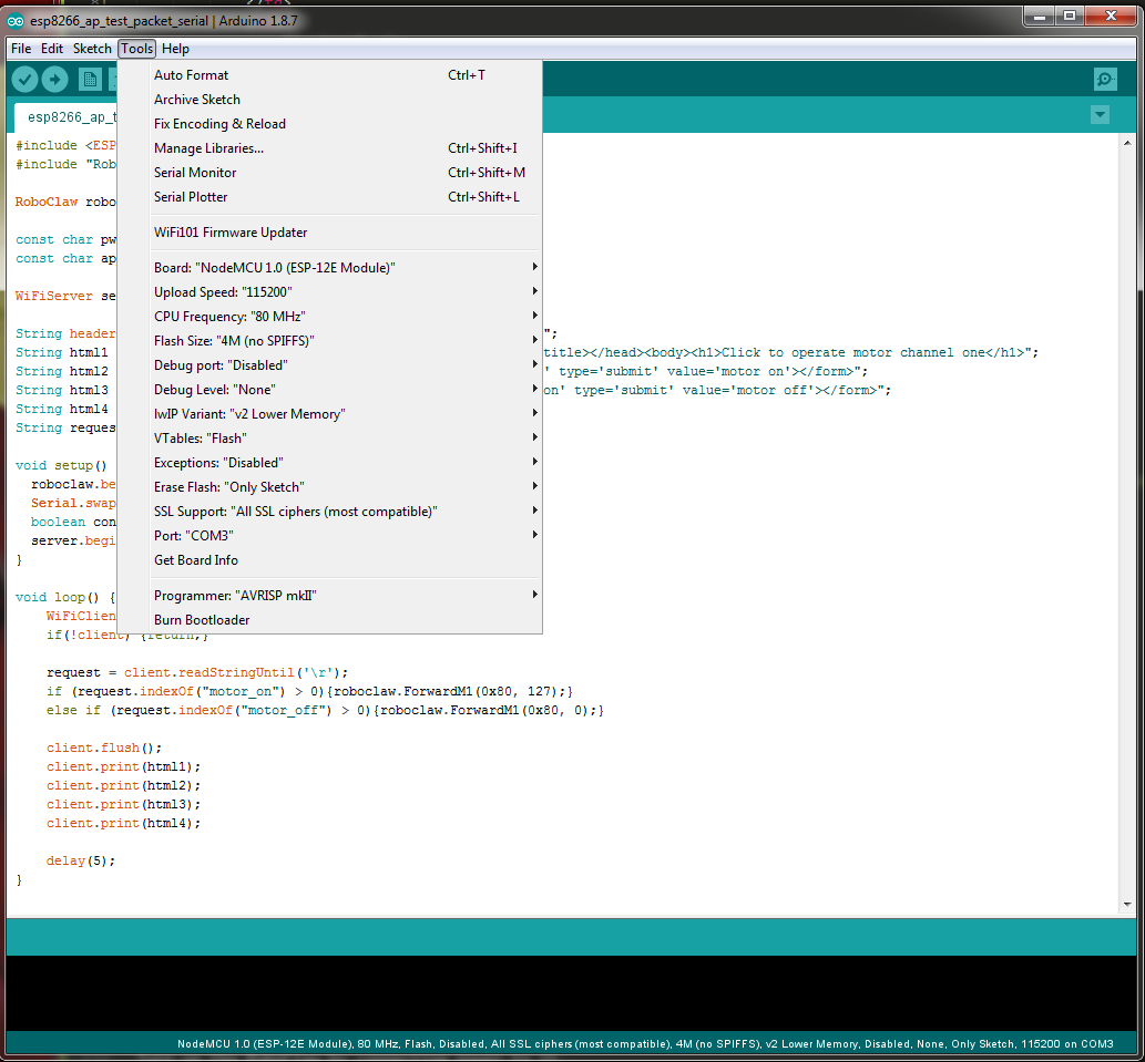
Figure 6: The board settings for the NodeMCU board in the Arduino IDE. Note that the port number will vary from system to system.
11. The example code for this app note can be
downloaded from GitHub or cloned from the commandline if Git is installed on the computer being used.
To clone the code repository enter the following on the commandline:
git clone https://github.com/basicmicro/roboclaw_esp8266_advanced.git
12. Turn on the RoboClaw by connecting power to it.
13. In the Arduino IDE open the example code for this app note. Click on the right-hand arrow button to compile the code and upload it to the esp8266.
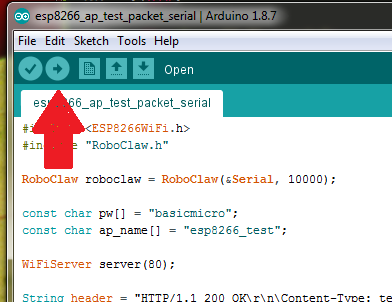
Figure 7: Location in the Arduino IDE to compile and upload to the board.
14. Using a computer, tablet or phone connect to the access point named “esp8266_test” and enter the password “basicmicro” (without quotes). Open a browser and navigate to “192.168.4.1”. A webpage should be displayed with two buttons, one to turn the motor on and another to turn the motor off. If nothing happens after pressing the buttons make sure that the serial lines are not wired up backwards and that there is a ground connection between the esp8266 and the RoboClaw. Finally make sure that the mode and serial settings in Motion Studio match those in the example code.
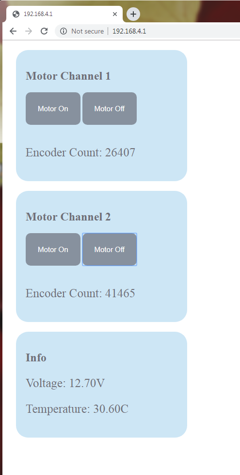
Figure 8: The webpage for controlling a RoboClaw.
Figure 9: The web interface in action.
The example web interface has been tested in the Chrome browser. It is recommended to also run this example code in Chrome.
Code Walkthrough
Below the important sections of the example code are listed and discussed.
#include <ESP8266WiFi.h>
#include <WiFiClient.h>
#include <ESP8266WebServer.h>
#include “RoboClaw.h”
These four lines are include statements that bring additional code in to the program. The first three include statements include code that implement the wifi and server functionality of the es8266. The final include statement includes the RoboClaw Arduino library.
RoboClaw roboclaw(&Serial, 10000);
The line of code creates a RoboClaw object by calling the constructor and passing the address of the Serial object as well as a timeout value 10,000 milliseconds (10 seconds).
void setup() {
roboclaw.begin(38400);
Serial.swap();
WiFi.softAP(ap_name, pw);
server.on(“/”, handleHome);
server.on(“/readEncoder_1”, handleEncoder_1);
server.on(“/readEncoder_2”, handleEncoder_2);
server.on(“/readTemp”, handleTemp);
server.on(“/readVoltage”, handleVoltage);
server.on(“/handleMotor”, handleMotor);
server.begin();
}
In the setup function a handful of things are done. First the roboclaw serial communication is started at a baudrate of 38,400 bps. Next, the swap function is called on the Serial object to remap the serial pins to the ones used in this app note. The wifi access point is started next with the password and name defined earlier. The calls to server.on() map URLs to functions defined in the code. Lastly, the server is started with a call to server.begin().
void loop() {
server.handleClient();
}
Inside the loop function the server is called to handle client connections.
void handleHome(){
String page = home_page;
server.send(200, “text/html”,page);
}
This is the function that handles the root URL path. It simply sends the html content for the page as well as the css and javascript.
void handleEncoder_1(){
int enc_value = roboclaw.ReadEncM1(0x80);
String value = String(enc_value);
server.send(200, “text/plain”, value);
}
This function is called when the URL path of readEncoder_1 is accessed. The code calls the ReadEncM1 function on the roboclaw object and sends the value of encoder channel 1. An AJAX call is eventually used to access this value and write it to the webpage.
void handleEncoder_2(){
int enc_value = roboclaw.ReadEncM2(0x80);
String value = String(enc_value);
server.send(200, “text/plain”, value);
}
This function is called when the URL path of readEncoder_2 is accessed. If functions like the previous function except is grabs and returns the value of the second encoder channel.
void handleMotor(){
String motor_channel = server.arg(“motorChannel”);
String motor_state = server.arg(“motorState”);
if(motor_channel == “1”) {
if(motor_state == “1”) {
roboclaw.ForwardM1(0x80, 64);
}
else if(motor_state == “0”) {
roboclaw.ForwardM1(0x80, 0);
}
}
else if(motor_channel == “2”) {
if(motor_state == “1”) {
roboclaw.ForwardM2(0x80, 64);
}
else if(motor_state == “0”) {
roboclaw.ForwardM2(0x80, 0);
}
}
}
This function is called when the URL path of handleMotor is called. When the path is accessed two arguments are sent, motorChannel and motorState. The code above contains nested conditional statements that handle the combinations of the motorChannel and motorState values. Depending on the state and channel received by the function a given motor channel is either turned on or off by a call to either ForwardM1 or ForwardM2.
void handleTemp() {
uint16_t temp = 0;
roboclaw.ReadTemp(0x80, temp);
float temp_f = (float)temp/10;
String temp_str = String(temp_f);
server.send(200, “text/plain”, temp_str);
}
This function is called when the URL path of readTemp is accessed. The ReadTemp function is called on the roboclaw object and the value stored in the variable passed to it. The temperature value is later fetched by an AJAX call to the URL.
void handleVoltage() {
int voltage = 0;
voltage = roboclaw.ReadMainBatteryVoltage(0x80);
float voltage_f = (float)voltage/10;
String voltage_str = String(voltage_f);
server.send(200, “text/plain”, voltage_str);
}
This function is called when the URL path of readVoltage is accessed. The ReadMainBatteryVoltage function is called on the roboclaw object and the battery voltage is returned by the function and stored in an integer variable. The voltage value is later fetched by an AJAX call to the URL.
function sendCommand(chan,state) {
var xhttp = new XMLHttpRequest();
xhttp.onreadystatechange = function() {
if (this.readyState == 4 && this.status == 200) {
}
};
xhttp.open(“GET”, “handleMotor?motorChannel=”+chan+”&motorState=”+state, true);
xhttp.send();
}
This javascipt function is called when a user pressed a motor control button in the interface. An AJAX call is made to the handleMotor path passing the chan and state arguments. The anonymous callback function does nothing as there isn’t anything to do other than make a call to the path.
function getEnc_1() {
var xhttp = new XMLHttpRequest();
xhttp.onreadystatechange = function() {
if(this.readyState == 4 && this.status == 200){
document.getElementById(“encoder_1_value”).innerHTML = this.responseText;
}
};
xhttp.open(“GET”,”readEncoder_1″,true);
xhttp.send();
}
function getEnc_2() {
var xhttp = new XMLHttpRequest();
xhttp.onreadystatechange = function() {
if(this.readyState == 4 && this.status == 200){
document.getElementById(“encoder_2_value”).innerHTML = this.responseText;
}
};
xhttp.open(“GET”,”readEncoder_2″,true);
xhttp.send();
}
These two javascript functions make an AJAX call to their respective URL paths. They both fetch encoder values and then write the values to their respective html elements in the web interface.
function getTemp() {
var xhttp = new XMLHttpRequest();
xhttp.onreadystatechange = function() {
if(this.readyState == 4 && this.status == 200){
document.getElementById(“temp”).innerHTML = this.responseText;
}
};
xhttp.open(“GET”,”readTemp”,true);
xhttp.send();
}
This javascript function calls the path readTemp and fetches the motor controller’s temperature. Once the value has been fetched it updated the temp element in the web interface.
function getVoltage() {
var xhttp = new XMLHttpRequest();
xhttp.onreadystatechange = function() {
if(this.readyState == 4 && this.status == 200){
document.getElementById(“voltage”).innerHTML = this.responseText;
}
};
xhttp.open(“GET”,”readVoltage”,true);
xhttp.send();
}
This javascript function calls the path readVoltage and fetches the motor controller’s main battery voltage. Once the value has been fetched it updates voltage element in the web interface.
setInterval(function(){
getEnc_1();
}, 1000);
setInterval(function(){
getEnc_2();
}, 1000);
setInterval(function(){
getTemp();
}, 5000);
setInterval(function(){
getVoltage();
}, 2000);
These four calls to setInterval cause the javascript functions set in them to fire off automatically on a regular basis. The integer value passed to them tells the browser how often to call the functions in milliseconds. The values of encoder channel 1, encoder channel 2, temperature and main battery voltage are fetched and the webpage updated on a regular basis while the page is open.