Introduction
In a
previous Application Note code running on an A-Star microcontroller was used to control a RoboClaw in packet serial mode. This App Note expands on this by reading encoder values from the RoboClaw and displaying them on the LCD screen that is available for the A-Star board. A discussion of the example code is included at the end of this App Note.
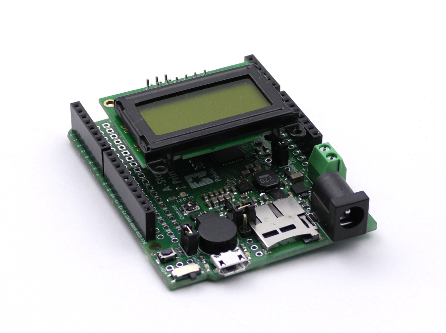
Figure 1: The A-Star board with LCD screen attached.
Materials
(1)
RoboClaw motor controller
(1)
Pololu A-Star 32U4 board
(1) LCD for A-Star board
(1 or 2)
Pololu gearmotors motors
(1) battery or power supply
(3) male to female jumpers
(1) small screwdriver
(1) computer with Arduino IDE and Motion Studio installed
1. First, if this is the first time an A-Star will be used with a given computer there are a few things that need to be done. If it’s a Windows machine the driver for the board will need to be installed. Also, the Arduino IDE requires some set up steps to be used with an A-Star board. The instructions for carrying out these steps can be
found here. Refer to section 4 of the document to learn how to set up a system for use with the A-Star board.
2. Next, the RoboClaw library must be added to the Arduino IDE. See
this tutorial for instructions on how to do so.
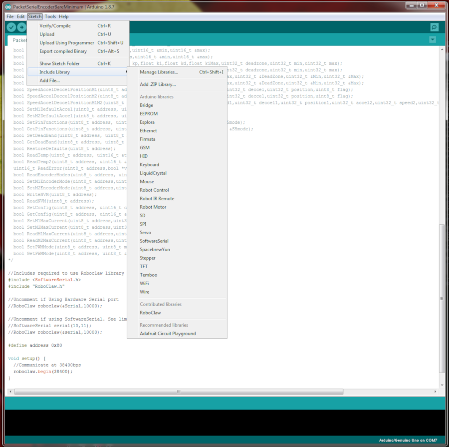
Figure 1: Adding the RoboClaw library to the Arduino IDE.
3. Power and one or two motors must be wired to the RoboClaw before beginning the process of wiring the A-Star and RoboClaw together. Motion Studio should also be used to verify that the controller and motor work properly before proceeding. Follow
this tutorial to step 10 to do so.
4. See
this tutorial on how to wire up a motor’s encoders to the RoboClaw.
5. Ensure that power to the RoboClaw and A-Star is disconnected before moving on to the next step.
6. A serial connection must be wired up between the A-Star and the RoboClaw boards. Three 0.1″ female to male jumper wires can be used to do so. Consult the table below for a list of the connections that must be made.
|
Function |
A-Star |
RoboClaw |
|
Receive |
Pin 0 |
S2 signal pin (pin closest to edge of board) |
|
Transmit |
Pin 1 |
S1 signal pin (pin closest to edge of board) |
|
Ground |
Any ground pin |
Any ground pin on the pin header |
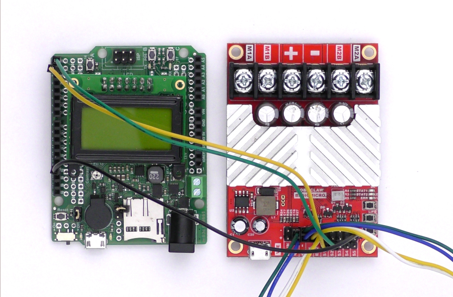
Figure 2: The serial port of the A-Star wired to the RoboClaw.
7. Connect the RoboClaw to the computer with a USB cable and reconnect power to the RoboClaw as done previously.
8. Open Basicmicro Motion Studio and connect the RoboClaw in use. Click on the left-hand pane titled “General Settings”. Find the area labeled “Setup” and set the Control Mode to Packet Serial. Now find the area labeled “Serial”. Set the field labeled Packet Serial Address to 128. Finally, in the same area, set the field titled Baudrate to 38400.
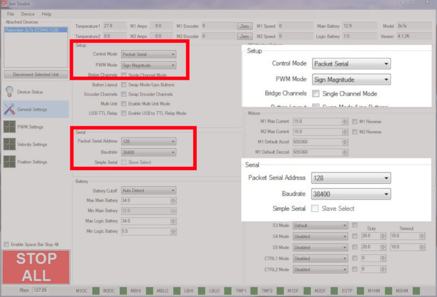
Figure 3: Setting the serial settings in Motion Studio.
9. Download the code for this tutorial
from here or clone it from GitHub if Git is installed on the machine being used.
To clone the repository from GitHub run the following on the command line while in a folder or directory suitable for storing it.
git clone https://github.com/basicmicro/astar_lcd.git
10. Connect the A-Star board to the computer with a USB cable. Note the port that it is using in the system’s device manager.
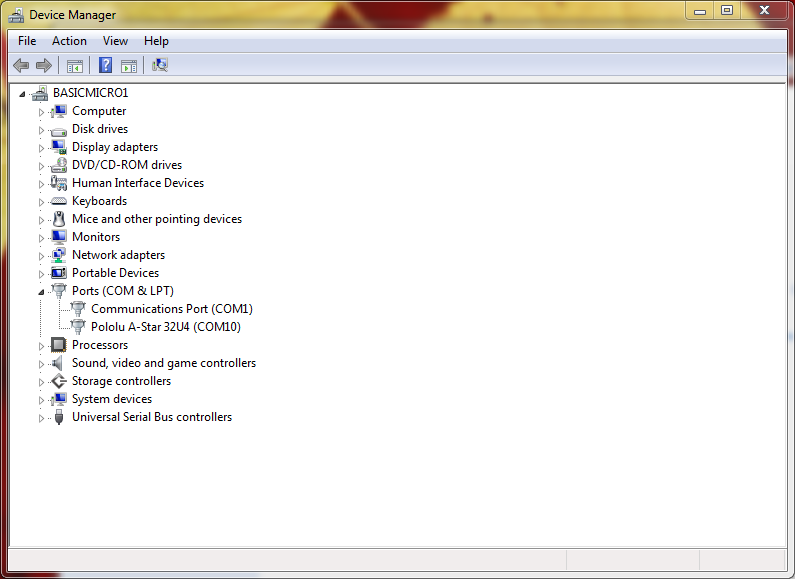
Figure 4: The device manager in Windows showing the A-Star com port.
11. Load the Arduino sketch up in the Arduino IDE. Set the board and port being used in the IDE. Once the code is open and the IDE is configured, upload the sketch to the board. The code will be compiled, loaded on to the board and begin running. If everything worked properly the motor attached to channel 1 of the RoboClaw will run in the forward direction at full speed for 2 seconds and then pause for two seconds before the process repeats. Simultaneously the encoder count for motor channel 1 will be displayed on the LCD screen.
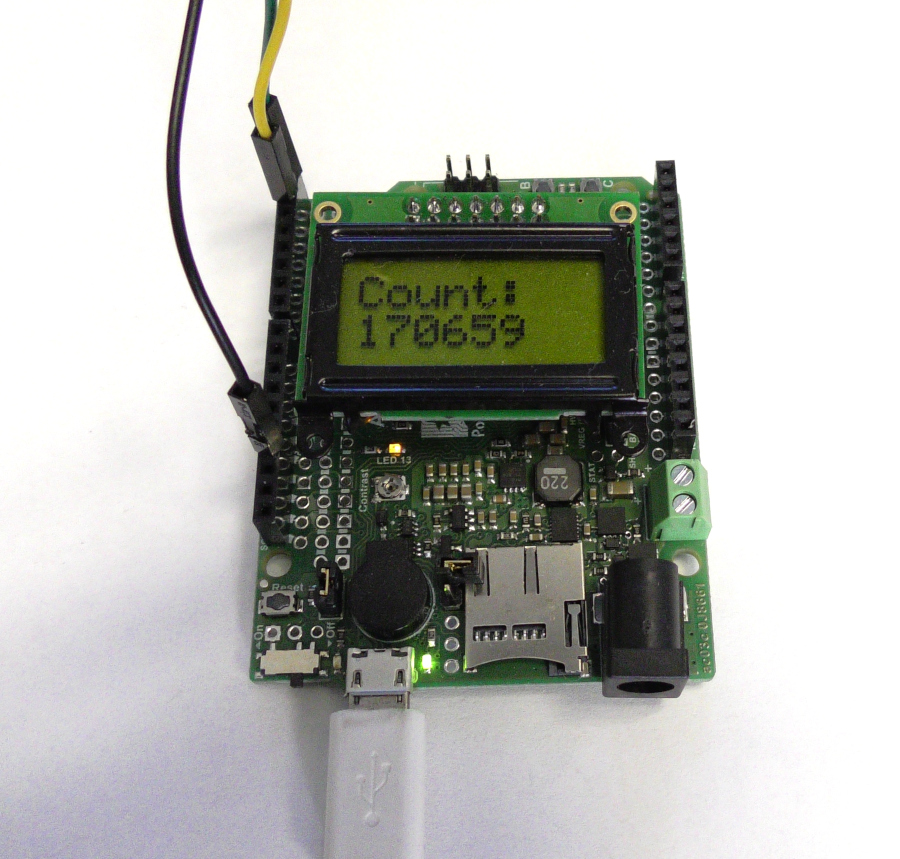
Figure 5: The encoder count for motor channel 1 displayed on the LCD screen.
Code Walkthrough
The first two lines of the program include the library for the A-Star LCD screen and the RoboClaw library.
#include <AStar32U4LCD.h>
#include “RoboClaw.h”
The next two lines of code create the object for the LCD screen and the roboclaw object. Note that the address of the serial port and a timeout value in milliseconds is passed to the RoboClaw constructor.
AStar32U4LCD astar;
RoboClaw roboclaw(&Serial1, 10000);
In the setup function two things happen: the RoboClaw’s serial communication is started and the LCD screen is initialized.
void setup() {
roboclaw.begin(38400);
astar.initPins();
astar.init();
}
The get_display_counts function is used in the main loop to read the encoder count of motor channel 1 and then display it on the LCD screen. The encoder count is found by calling ReadEncM1 on the roboclaw object and the returned value is converted to a string. The length of the returned string is then found. The string value and the length of the string are then used to write the encoder value to the LCD.
void get_display_counts(void) {
delay(100);
String enc_count = String(roboclaw.ReadEncM1(0x80));
int enc_length = enc_count.length();
astar.write(count.c_str(), 6);
astar.setCursor(0,1);
astar.write(enc_count.c_str(), enc_length);
delay(2000);
}
In the loop function the RoboClaw is instructed to run the motor in the forward direction by a call to FowardM1 passing the address of the RoboClaw and the speed value. The encoder count is retrieved and display by a call to get_display_count and then the LCD screen is cleared. The second block of code repeats this process but the motor is stopped in the call to ForwardM1 by passing a speed value of 0.
void loop() {
roboclaw.ForwardM1(0x80, 64);
get_display_counts();
astar.clear();
roboclaw.ForwardM1(0x80,0);
get_display_counts();
astar.clear();
}