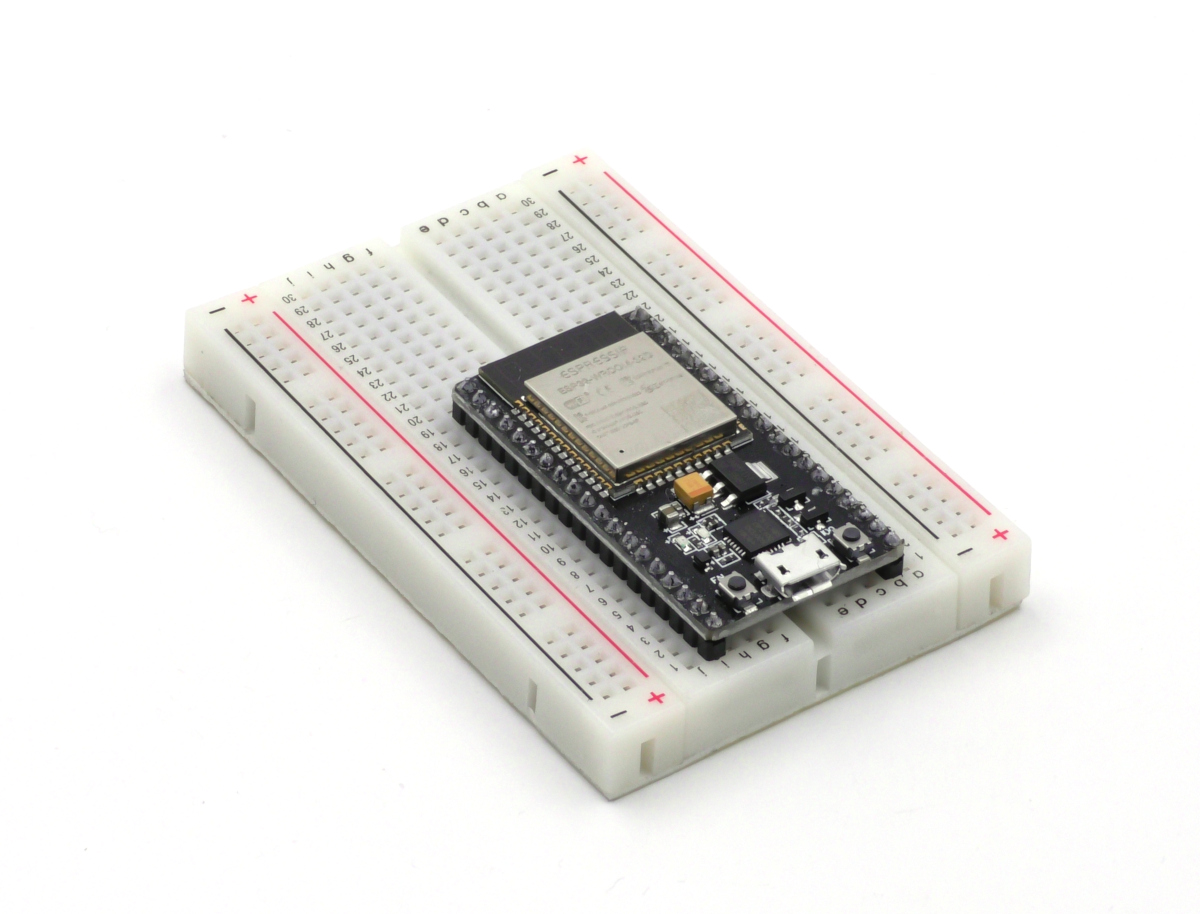
Figure 1: An ESP32 inserted in a breadboard.
Introduction
The ESP32 is the newer and more feature rich version of the popular ESP8266 wifi development board. Since the ESP32, like the ESP8266 has multiple built-in UARTs it can be used to control a RoboClaw motor controller in packet serial mode. The 32’s microcontroller can be used sans the wifi interface to write control logic for a RoboClaw or used with the wifi functionality to allow remote control of any project featuring a RoboClaw. This Application Note walks through configuring a RoboClaw, an ESP32 and the Arduino IDE so that two demo programs can be loaded and run to test out the functionality of the ESP32/RoboClaw combination. The example code can also be used as a jumping off point to develop applications for the RoboClaw.
Materials
(1) RoboClaw motor controller
(2) DC brushed motors
(1) power source for RoboClaw
(1) ESP32 board (NodeMCU board used in this Application Note)
(1) breadboard
(2) female to male 0.1″ jumper cables
(1) micro USB cable
(1) computer with Motion Studio and Arduino IDE installed
(2) DC brushed motors
(1) power source for RoboClaw
(1) ESP32 board (NodeMCU board used in this Application Note)
(1) breadboard
(2) female to male 0.1″ jumper cables
(1) micro USB cable
(1) computer with Motion Studio and Arduino IDE installed
Instructions
1. Follow this Application Note to step 10 to wire the motors and power to the RoboClaw.
2. If the motors being used have encoders see this Application Note for instructions on wiring them to a RoboClaw.
3. Follow steps 14-16 of this Application Note to configure the RoboClaw with Motion Studio.
4. Place the ESP32 in the breadboard so that connections can be made to it with jumper wires.
5. Using two jumper wires connect the serial port of the ESP32 to the RoboClaw. On the NodeMCU board used in the example GPIO 17 is wired to the signal pin on the S1 header and GPIO 16 is wired to the signal pin of the S2 header. If a different ESP32 board is being used consult the documentation to find the TX and RX pins of the serial port to be used. The S1 header of the RoboClaw is the RX side and the S2 header is the TX side. Be sure to connect the TX to the RX and the RX to the TX between the two boards.
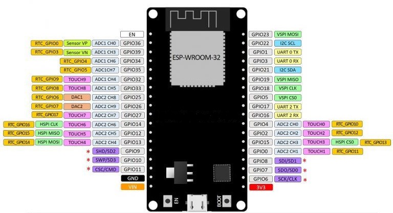
Figure 2: The GPIO ports of the ESP32 board used in this Application Note.
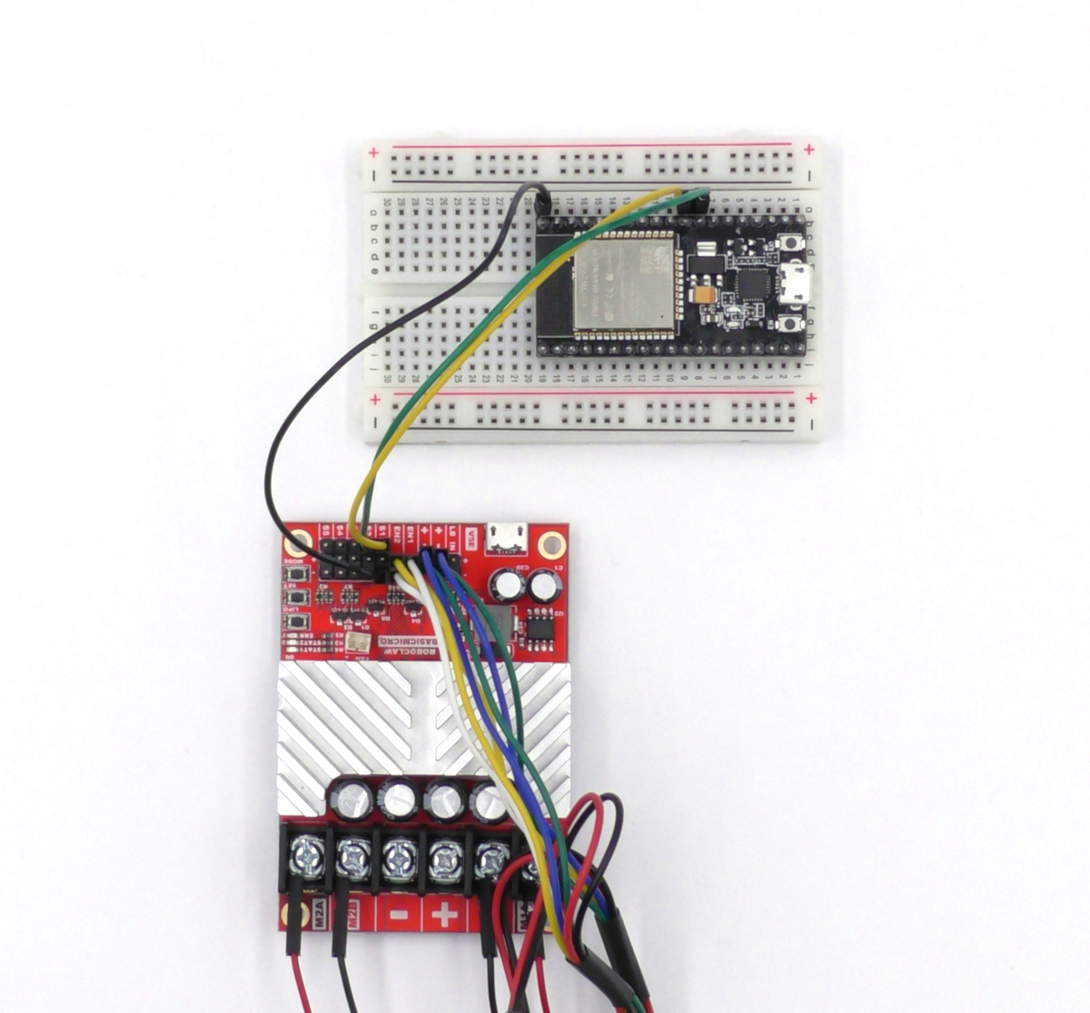
Figure 3: The serial ports of the RoboClaw and ESP32 wired together.
6. The RoboClaw library must be added to the Ardino IDE before any example code is loaded and run. Follow the section titled “Adding the RoboClaw library to the Arduino IDE” in this Application Note.
7. Before using the ESP32 for the first time and loading code on to the board the ESP32 library must be added to the Arduino IDE. Begin by opening the Arduino IDE, select “File” and then “Preferences” in the menu at the top of the IDE. In the text box labeled “Board Manager URLs” add the URL below. Be sure to add a comma between entries if any other URLS are in the text box. Click “OK” when done.
https://dl.espressif.com/dl/package_esp32_index.json
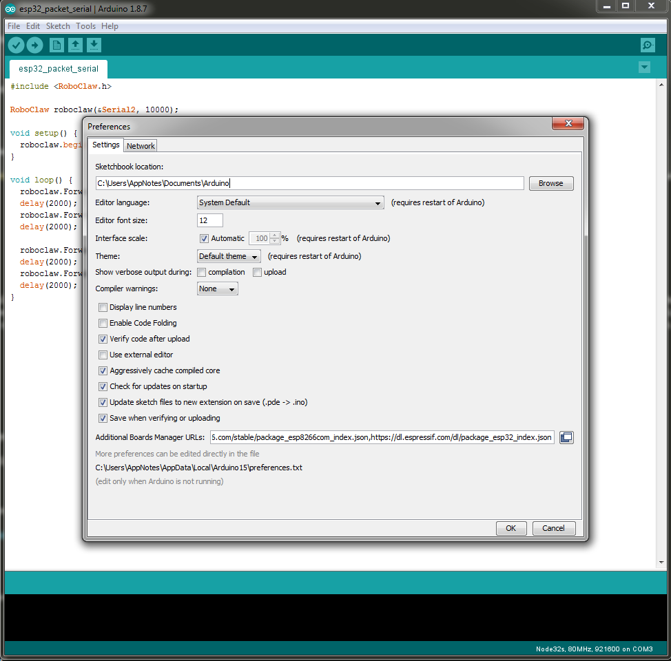
Figure 4: The location in the Arduino IDE where the board URL is placed.
“Board” > “Board Manager” in the menu at the top of the IDE. Search for “ESP32” and install the library. It will take several minutes for the library to be downloaded and installed.
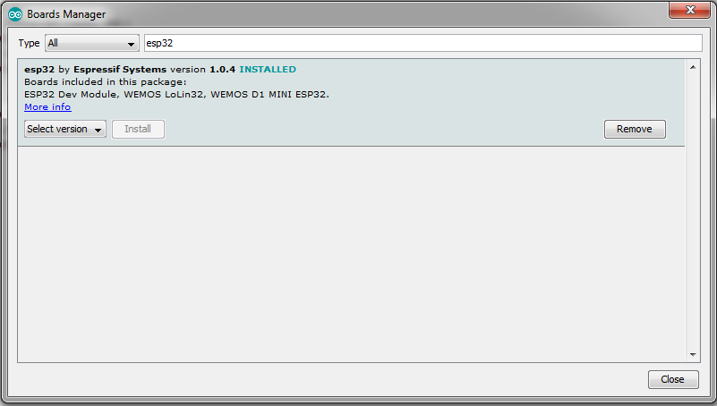
Figure 5: The Arduino IDE board manager.
8. Connect the ESP32 board to a computer with a micro USB cable. This will power the board as well as allow for it to be programmed.
9. Now that the Arduino library is installed the IDE needs to be configured for the board and port in use. Go to “Tools” > “Board” in the menu at the top of the application. in the section labeled “ESP32 Arduino” select the board being used. The board used in this example is listed as “Node32s”. Once the board has been set the “Port” option in the same board menu. The Control Panel section of Windows has a section called the Device Manager, it will list what port is being used by the USB to TTL adapter of the ESP32 board.
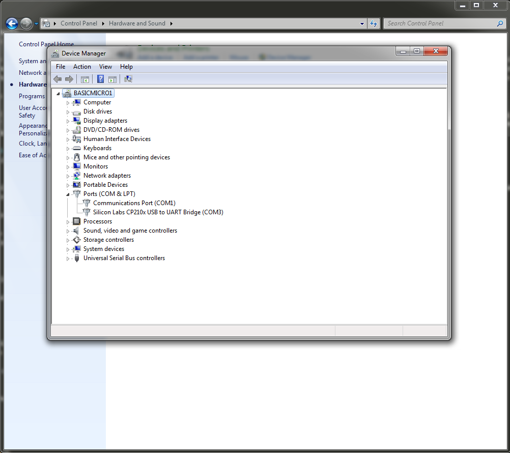
Figure 6: The Windows device manager where port assignments can be checked.
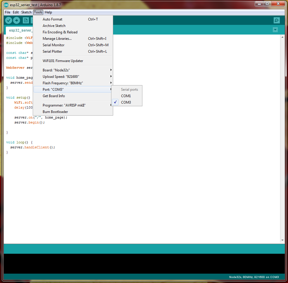
Figure 7: The board settings in the Arduino IDE Tools menu.
10. Finally the code to be run must be compiled and flashed to the board. The example code for this application note can be downloaded or cloned from GitHub here. There are two example file that can be flashed to the board. One example is a simple demo of the packet serial mode usage and the other is a full blown example of a web interface used to control both motor channels as well as read the encoder and other data from the board.
To flash a program to the ESP32 board begin by opening the desired file in the Arduino IDE. Click the button with the arrow in it above the code editing area. The code will be compile and then the flashing process will begin. On some boards, including the one used in this app note the boot button on the board must be held done will the IDE flashes the code. Check the documentation for the board in use. Finally, on some boards a reset/enable button must be pressed to being running the newly flashed code, once again check the documentation for the board in use for further instructions.
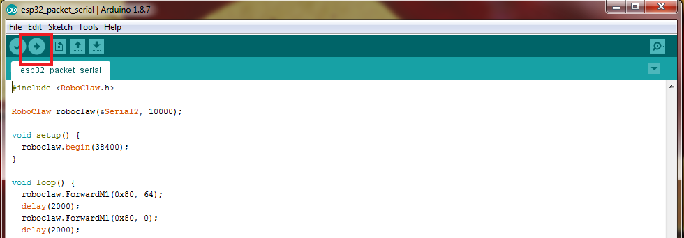
Figure 8: The button to compile and upload code the ESP32 highlighted.
Example Code
Packet Serial Demo
This example utilizes the packet serial mode of the RoboClaw to sequentially turn motor channel 1 and 2 on and off in the forwards direction. This example does not use any of the wifi functionality of the ESP32, just the microcontoller sending commands to the RoboClaw over the serial port. A survey of the packet serial commands for the RoboClaw can be found here. Use this example as a starting point to explore using packet serial to control RoboClaw.
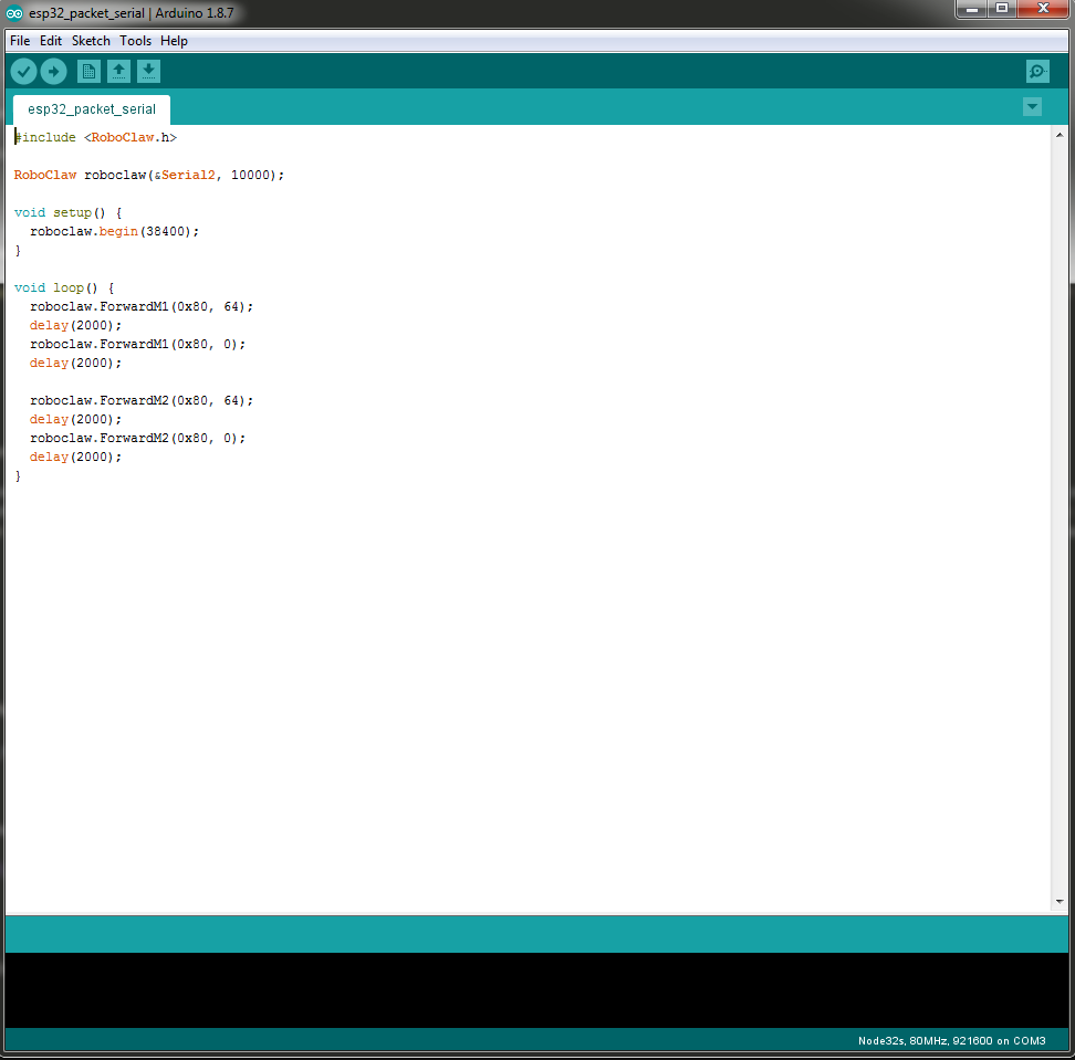
Figure 9: The standalone packet serial example code in the Arduino IDE.
Web Interface for Motor Control
This example also uses packet serial to control the attached RoboClaw but also features a web interface that can be accessed by connecting to the wifi access point configure in the code. Any device with a web browser and wifi connectivity should be able to utilize this demo. Once the ESP32 is turned on a wifi network named “esp32” should appear. Connect to it with the password “basicmicro”. Open a web browser and type “192.168.4.1” in the address bar, the interface will load and the motor controller can be operated from the web interface. The example code is similar to the one used in the ESP8266 article and a walkthrough of the code can be found here. The only difference in the code used in this article and the code walkthrough linked to is a change in the header files included.

Figure 10: The web interface example code in the Arduino IDE.
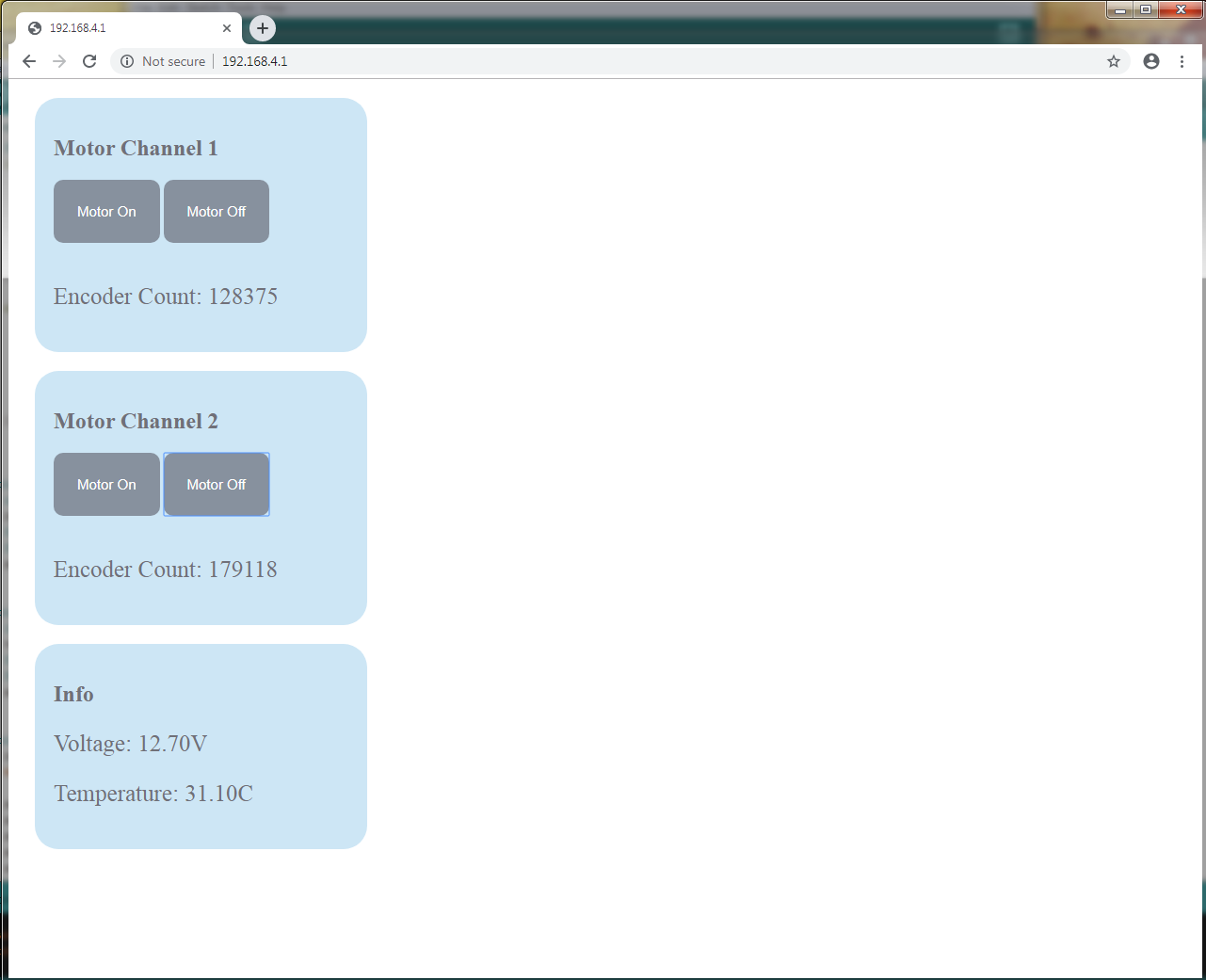
Figure 11: The web interface displayed by the example code.