
A dual channel RoboClaw can drive two brushed DC motors from a single board and is configured with BasicMicro’s free Motion Studio software. Setup takes four stages: wire the motors and optional encoders, connect power, install Motion Studio over USB, and select a control mode.
What You Need
- 1× Dual channel RoboClaw motor controller
- 1–2× Brushed DC motor (with quadrature encoders, optional)
- 1× Battery or power supply
- 1× Micro USB cable
- 1× Small screwdriver for the screw terminals
- 1× Computer running Windows 10 or 11 with Motion Studio installed
Wiring the RoboClaw
-
Begin by wiring the motors to the RoboClaw. Dual channel RoboClaws have two motor channels and can be used with both channels wired or only one. The terminals labeled M1A and M1B are for motor channel 1 and the terminals labeled M2A and M2B are for motor channel 2. Strip the ends of the motor wires, insert the ends into the screw terminals and tighten the screws down with a screwdriver.
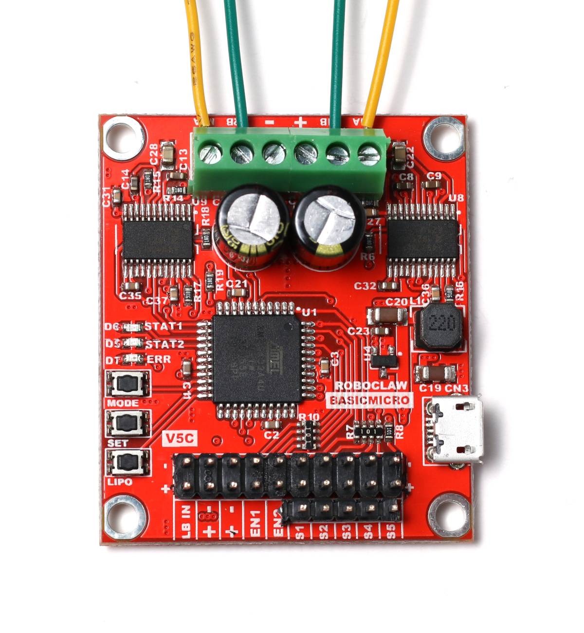
Figure 2: Motors wired to the 7A RoboClaw. 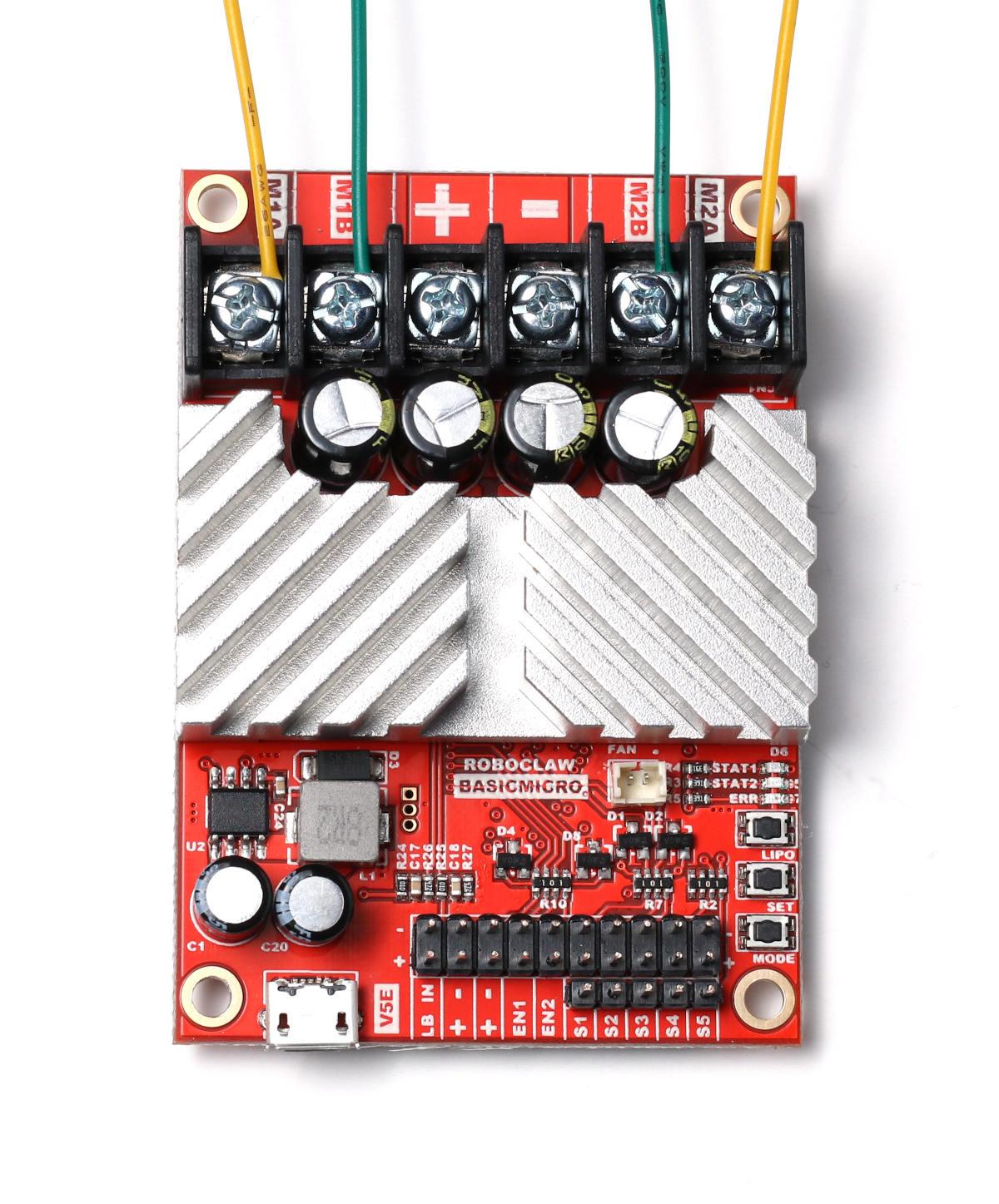
Figure 3: Motors wired to the 30A RoboClaw. -
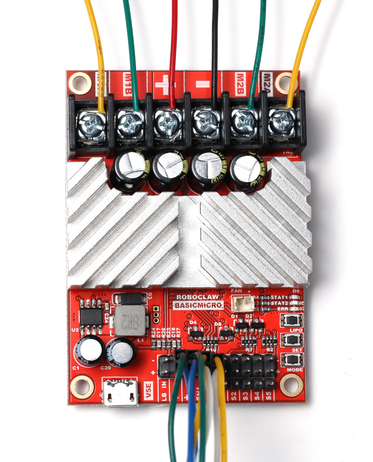
If encoders are being used, wire them to the RoboClaw now; if encoders are not being used, skip this step. The pin headers labeled EN1 and EN2 are used to connect the signal lines of the encoders. EN1 corresponds to motor channel 1 and EN2 corresponds to motor channel 2. Connect the two signal lines from each encoder to the encoder header for a given motor channel. Next to the encoder pins are pins for 5V power and ground. Connect the power pin of the encoder to the 5V pin and the ground pin of the encoder to the ground pin on the header.
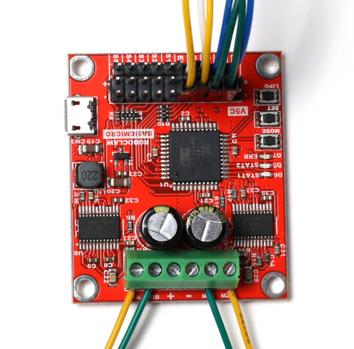
Figure 4: Encoders wired to the 7A RoboClaw. 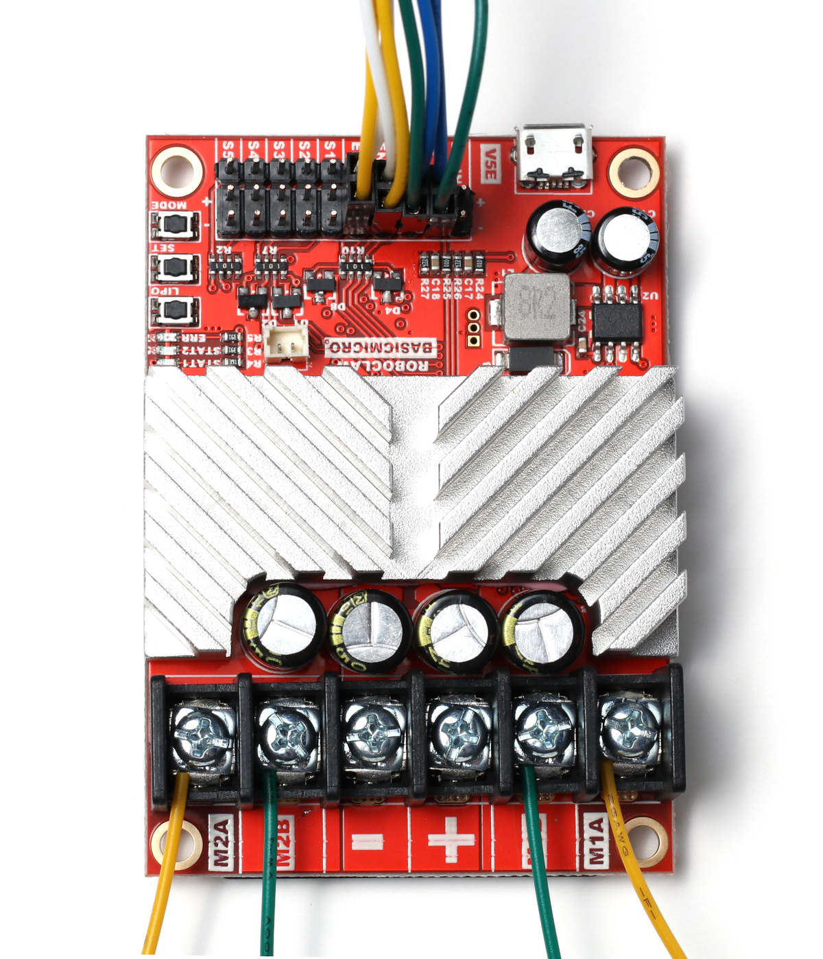
Figure 5: Encoders wired to the 30A RoboClaw. -
Wire the power source to the RoboClaw; either a battery or conventional power supply can be used. The positive wire is inserted in the terminal labeled (+) and the negative in the terminal labeled (-). If a connector is being used between the power source and the RoboClaw, ensure that it is rated for the maximum current of the motor(s). The battery settings for the RoboClaw should be set according to this app note.
Do not wire the power source backwards or the RoboClaw will be permanently damaged.
If the RoboClaw will be controlling a large load or quickly starting and stopping, a battery is recommended due to the large regenerative voltage created in these situations. Most power supplies cannot absorb this regenerative voltage. Setting the RoboClaw’s Max Main Battery voltage about 2 VDC above the supply’s output voltage often resolves this. If overvoltage faults persist, a voltage clamp with a dump resistor may be required.
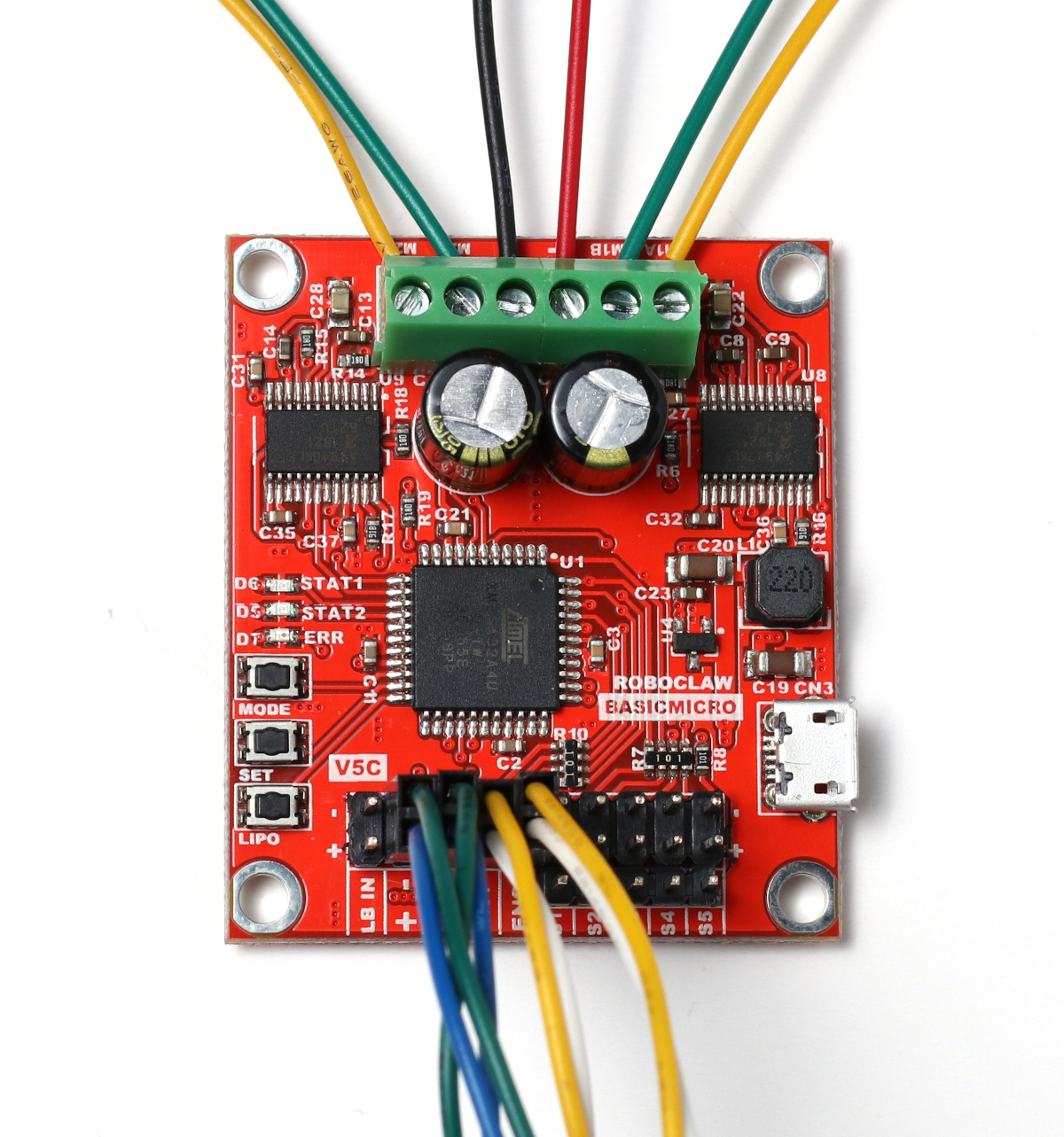
Figure 6: Power wired to the 7A RoboClaw. Figure 7: Power wired to the 30A RoboClaw.
Installing Motion Studio
-
Once power has been connected to the RoboClaw, turn the power source on to power the RoboClaw. Connect a micro USB cable between the RoboClaw and a computer running Windows 10 or 11. The USB cable does not supply power to the RoboClaw.
Next, the USB driver and Motion Studio must be installed on the computer in use. Motion Studio is used to configure and test RoboClaw motor controllers. See this application note for instructions on installing the USB driver and Motion Studio.
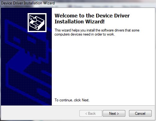
Figure 8: Installation of the USB driver.
Testing the Motors and Encoders
-
Open Motion Studio and connect the RoboClaw by clicking “Connect Selected Unit” in the upper left-hand side of the application. Click on PWM Settings in the left-hand side of the application. Locate the sliders for motor 1 and motor 2. Move each slider up and down and make sure the motors respond when moving the sliders. A motor should turn in the forward direction when moving the slider up and backwards when moving the slider down. If a motor does not move the proper direction, power down the RoboClaw and reverse the motor connections for that channel or reverse the motor direction in the General Settings window. Repeat this step until each motor operates properly.
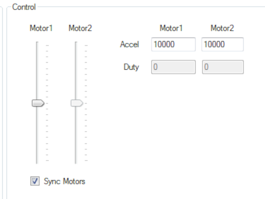
Figure 9: The motor control sliders. -
If encoders have been wired to the RoboClaw, they must be tested in Motion Studio; if encoders are not being used, skip this step. While still in the PWM Settings window, locate the text boxes at the top of the application labeled “M1 Encoder” and “M2 Encoder”. Move the slider for a motor channel up and check that the encoder count is increasing in a positive direction. Then move the slider down and check that the encoder count is decreasing. Repeat for the second motor if it is being used. If the count direction is not correct, reverse the encoder signal lines on the pin header. Remember, EN1 is for motor channel 1 and EN2 is for motor channel 2.
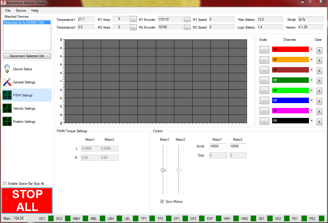
Figure 10: The encoder counts are at the top of the application window. -
Next, the encoder and motor combination must be tuned for velocity control or position control. If encoders are not being used, skip this step. See this application note for instructions on tuning.
Setting the Control Mode
-
The control mode must be set correctly for the mode of operation desired. Click on General Settings on the left-hand side of the application, locate the pane labeled Setup, and set the dropdown labeled Control Mode to the desired mode.
Control Mode Used With Packet Serial Microcontrollers via the available libraries Simple Serial Microcontrollers, simplified command set RC RC radios and receivers Analog Joysticks, potentiometers, and other analog devices 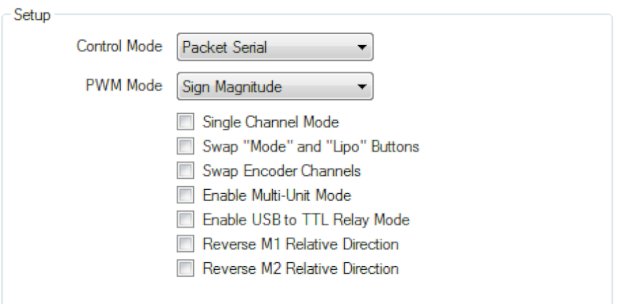
Figure 11: The location of the control mode setting. -
Save the settings to the board by clicking “Device” in the menu at the top of the application and then clicking “Write Settings”.
Next Steps
More information on using each mode can be found in our application notes. Some additional wiring and software configuration must be done for some modes.
- Packet serial: Using Arduino with RoboClaw and Using the Arduino Library
- RC mode: Basic RC Mode Setup
- Analog mode: Analog Control


