
Getting started with a RoboClaw motor controller takes four stages: wire the motors and optional encoders, connect power, install Motion Studio and test the motors over USB, and set a control mode. This guide covers the process for all RoboClaw models, both dual channel and Solo.
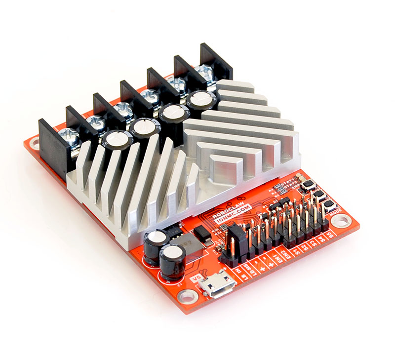
Some photos in this guide show an older RoboClaw revision with onboard configuration buttons. Button configuration is deprecated; all current RoboClaw models are configured with Motion Studio.
What You Need
- 1× RoboClaw motor controller
- 1–2× Brushed DC motors (with quadrature encoders, optional)
- 1× Battery or power supply
- 1× USB A to micro B cable
- 1× Computer running Windows 10 or 11 with Motion Studio installed
Wiring the Motors and Encoders
-
Wire one or two motors to the RoboClaw. On dual channel RoboClaws the first motor is wired to M1A and M1B and the second motor to M2A and M2B. On the RoboClaw Solo a motor is wired to motor channel 1.
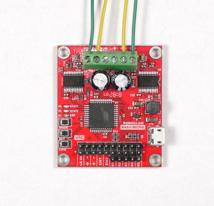
Figure 2: Wiring for both motor channels. -
If encoders are being used, wire them to the RoboClaw. On dual channel RoboClaws the encoder for motor channel 1 is wired to the EN1 header and the encoder for motor channel 2 is wired to the EN2 header. On the RoboClaw Solo a single encoder is wired to pins 1A and 1B on the pin header block.
Power for the encoder is available at the 5V pins on both the dual channel and single channel RoboClaws. Be sure to also connect the encoder’s ground pin to ground on the RoboClaw. Refer to the pinout diagram of the encoder in use for correct wiring; Pololu Encoder Wiring can be used as an example of wiring encoders.
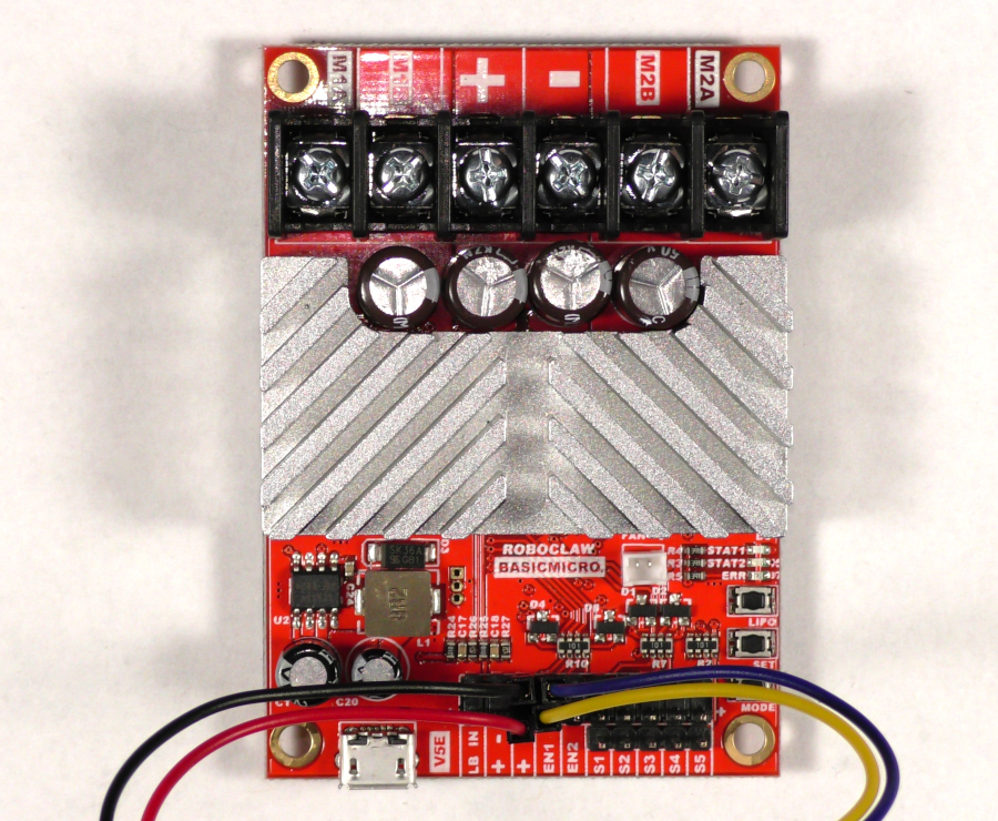
Figure 3: Power and signal wiring for one encoder channel.
Connecting Power
-
Connect a power supply or battery to the RoboClaw. The power terminals are labeled (+) for positive and (-) for negative. On the RoboClaw Solo the red lead is the positive connection and the black lead is the negative connection. The battery settings for the RoboClaw should be set according to Configuring RoboClaw Battery Settings.
Do not connect the power source backwards or the RoboClaw will be permanently damaged.
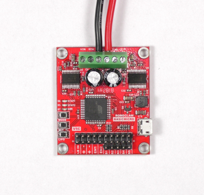
Figure 4: Power wiring for the RoboClaw.
Installing Motion Studio
-
Install Motion Studio by following Installing BasicMicro Motion Studio. Motion Studio installs from a single signed setup.exe, and no separate USB driver installation is required.
Turn on the RoboClaw’s power source, then connect the USB cable between the RoboClaw and the computer.
The USB cable does not power the RoboClaw; it is only used for communication between the RoboClaw and a computer. Power the RoboClaw from its main power source before connecting the USB cable.
Testing the Motors and Encoders
-
Open Motion Studio and connect to the RoboClaw by clicking “Connect Selected Unit” in the upper left-hand side of the application. Click on “PWM Settings” in the left-hand pane. Find the box labeled “Control” and slide the sliders for Motor 1 and/or Motor 2. The motors should turn when operating the sliders, forwards when sliding up and backwards when sliding down. If a motor does not turn the proper direction, reverse the wiring of that motor. Remove power from the RoboClaw before changing any wiring.
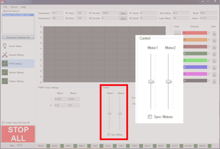
Figure 5: The PWM Settings motor sliders. -
If encoders are being used, test them while still in the PWM Settings window. Use the sliders labeled “Motor 1” and “Motor 2” to move the motors forwards and backwards. If the encoders are working properly, the “M1 Encoder” and “M2 Encoder” values at the top of the window should increment when the motor moves in the forwards direction and decrement in the backwards direction. If the encoder counts do not increment and decrement properly, reverse the encoder signal connections.
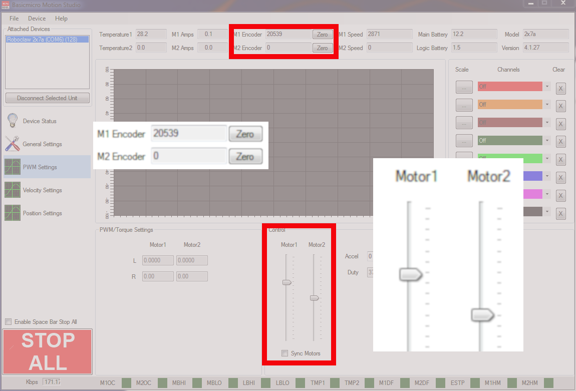
Figure 6: The location of the encoder counts in Motion Studio. -
If encoders have been wired, the motor and encoder combination must be tuned. There is an auto tuning routine in Motion Studio that can be used for velocity control or position control. See Auto Tuning with Motion Studio for instructions on auto-tuning. If position control is being tuned, be sure to set the minimum and maximum positions and check the range of motion after the tuning process.
Setting the Control Mode
-
Finally, the control mode and any options for the mode must be set in Motion Studio. Click on “General Settings” in the left-hand pane, find the area labeled “Setup”, and set the Control Mode to the desired mode. For example, if packet serial is being used to communicate with a microcontroller, set the Control Mode to Packet Serial, then set a baudrate and address in the area labeled “Serial”. Save the settings to the board by clicking “Device” in the menu at the top of the application and then clicking “Write Settings”. The guides in the next section cover the setup details for each control mode.
Next Steps
For a model-specific walkthrough with photos of each connection, see the quick start guide for the RoboClaw in use:
Each control mode has its own setup guide covering the wiring and Motion Studio options for that mode:
- Packet serial: Simple Arduino Control of the RoboClaw
- Standard serial: Standard Serial Mode with Arduino
- RC mode: RoboClaw RC Controlled Differential Drive Setup
- Analog mode: Analog Control with RoboClaw


