
The Pololu A-Star 32U4 Prime reads encoder counts from a RoboClaw motor controller over packet serial and displays them on its built-in LCD. Wire three jumpers between the boards, set the RoboClaw to packet serial mode in Motion Studio, and a short Basicmicro Arduino sketch runs the motor and updates the display.
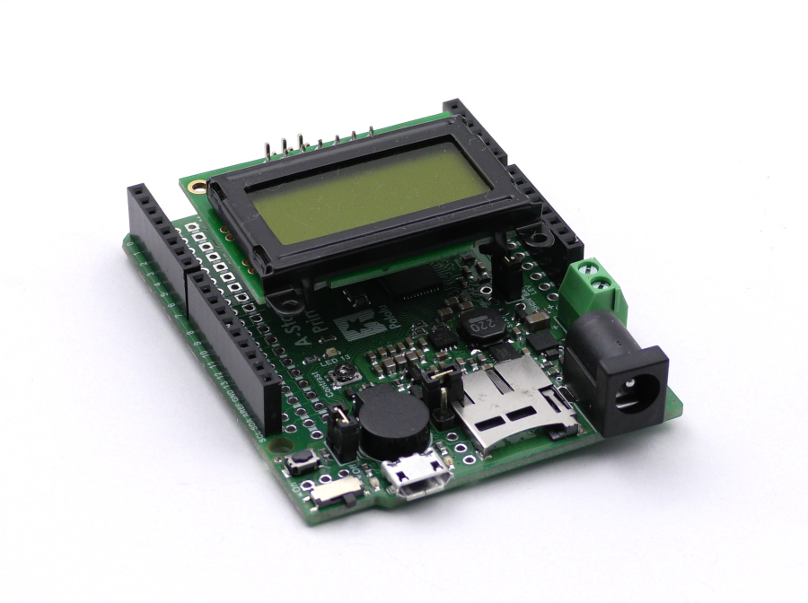
In RoboClaw Packet Serial with the Pololu A-Star 32U4, code running on an A-Star microcontroller controlled a RoboClaw in packet serial mode. This application note expands on that by reading encoder values from the RoboClaw and displaying them on the LCD screen available for the A-Star 32U4 Prime board. A walkthrough of the example code is included at the end.
The procedure works with any RoboClaw model and any motor with a quadrature encoder. The A-Star 32U4 Prime is available in configurations with an 8×2 character LCD preinstalled, and that LCD is what the sketch in this article writes to.
What You Need
- (1) RoboClaw motor controller
- (1) Pololu A-Star 32U4 Prime with LCD (any Prime configuration with the LCD works)
- (1 or 2) Pololu gearmotor with encoder
- (1) Battery or power supply
- (3) Male to female jumper wires
- (2) USB cables
- (1) Small screwdriver
- (1) Windows computer
How Do You Set Up the A-Star and Arduino IDE?
- If this is the first time an A-Star will be used with a given computer, a small amount of one-time setup is required. The Arduino IDE needs Pololu’s board support package installed, and Windows users can optionally install Pololu’s drivers so the board appears with a proper name in the Device Manager. The “Getting started” section (section 6) of the Pololu A-Star 32U4 User’s Guide covers both steps.
- Next, install the two libraries the sketch uses. In the Arduino IDE go to Sketch > Include Library > Manage Libraries, search for “Basicmicro” and click Install, then search for “AStar32U4” and install Pololu’s library as well. The Basicmicro library communicates with the RoboClaw, and the AStar32U4 library drives the LCD. See Using the RoboClaw Arduino Library for a complete walkthrough of the Basicmicro library.
How Is the RoboClaw Wired to the A-Star?
- Wire power and one or two motors to the RoboClaw before wiring the A-Star to it, and use Motion Studio to verify that the controller and motors work properly. The Dual Channel RoboClaw Quick Start Guide covers this process.
- Wire the motor’s encoder to the RoboClaw’s EN1 header as shown in Pololu Encoder Wiring. The encoder is required for this example, since its count is what the sketch displays.
- Ensure that power to the RoboClaw and the A-Star is disconnected before making the serial connections.
- Wire the serial connection between the A-Star and the RoboClaw using three male to female jumper wires, as shown in Figure 2. The table below lists the connections to make.
Function A-Star RoboClaw Receive Pin 0 S2 signal pin (pin closest to the edge of the board) Transmit Pin 1 S1 signal pin (pin closest to the edge of the board) Ground Any ground pin Any ground pin on the pin header 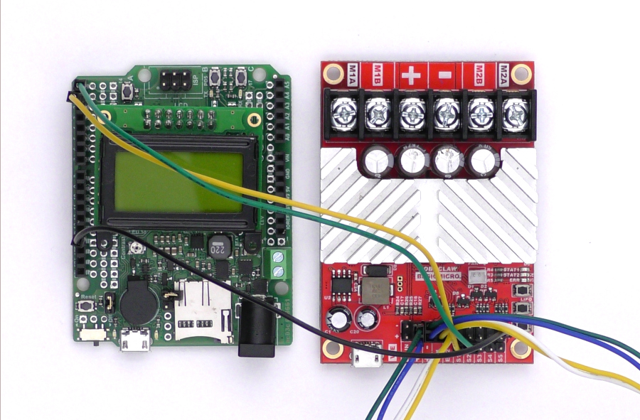
Figure 2: The serial port of the A-Star wired to the RoboClaw. - Connect the RoboClaw to the computer with a USB cable and reconnect power to the RoboClaw.
How Is Packet Serial Mode Configured in Motion Studio?
- Open Basicmicro Motion Studio and connect the RoboClaw in use. Click on “General Settings” in the left-hand pane. In the area labeled “Setup”, set the Control Mode to Packet Serial. In the area labeled “Serial”, set the Packet Serial Address to 128 and the Baudrate to 38400.
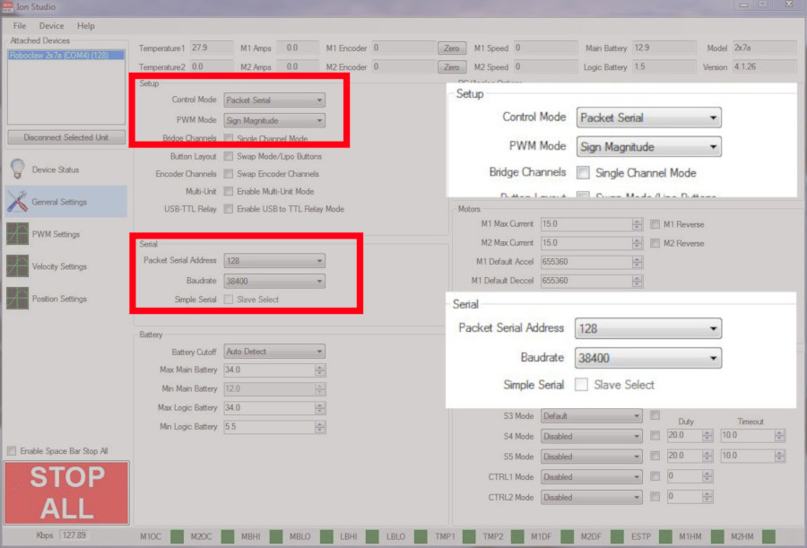
Figure 3: Setting the serial settings in Motion Studio.
How Do You Upload and Run the Example Sketch?
- Create a new sketch in the Arduino IDE and paste in the complete example below.
// Include the libraries for the A-Star LCD and the Basicmicro library #include <AStar32U4.h> #include <Basicmicro.h> // Packet serial address of the RoboClaw, set in Motion Studio #define ADDRESS 128 // Create the LCD object and the Basicmicro object using the A-Star's // Serial1 hardware serial port and a 10,000 microsecond timeout AStar32U4LCD lcd; Basicmicro controller(&Serial1, 10000); void setup() { // Start serial communication with the RoboClaw at 38400 baud controller.begin(38400); } void loop() { // Run motor 1 forward at about 50% power and show the count controller.DutyM1(ADDRESS, 16384); displayCount(); // Stop motor 1 and show the count again controller.DutyM1(ADDRESS, 0); displayCount(); } // Read the channel 1 encoder count and display it on the LCD void displayCount() { uint32_t count = controller.ReadEncM1(ADDRESS); // The A-Star LCD has 8 characters on each of its 2 lines lcd.clear(); lcd.print(F("Enc 1")); lcd.gotoXY(0, 1); lcd.print(count); delay(2000); } - Connect the A-Star board to the computer with a USB cable. In the Arduino IDE, select the A-Star 32U4 under Tools > Board and select the board’s port under Tools > Port.
- Upload the sketch to the board. Once the upload completes the sketch begins running. If everything is working properly, the motor attached to channel 1 of the RoboClaw alternates between running forward at about 50% power for 2 seconds and stopping for 2 seconds, while the LCD shows the channel 1 encoder count, updated at each change.
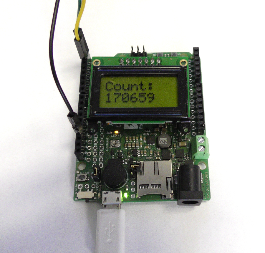
Figure 4: The encoder count for motor channel 1 displayed on the LCD screen.
Code Walkthrough
A walkthrough of the code shows how the sketch combines the two libraries.
The first two lines include the Pololu library for the A-Star board and the Basicmicro Arduino library.
#include <AStar32U4.h>
#include <Basicmicro.h>
The next two lines create the object for the LCD screen and the Basicmicro object. The LCD object needs no parameters. The Basicmicro constructor is passed a pointer to the A-Star’s Serial1 hardware serial object and the communication timeout in microseconds, so a value of 10000 sets a 10 millisecond timeout.
AStar32U4LCD lcd;
Basicmicro controller(&Serial1, 10000);Serial is the USB connection to the computer and Serial1 is the hardware serial port on pins 0 and 1. The two are independent, so the USB cable can stay connected while the sketch uses hardware serial. Using Hardware Serial with the RoboClaw Arduino Library lists the hardware serial port names and pins for other Arduino models.In the setup() function the begin() function of the Basicmicro object is called with the baud rate for serial communication, which must match the value set in Motion Studio. The LCD needs no initialization of its own; the Pololu library initializes the screen automatically the first time it is used.
controller.begin(38400);In the loop() function a motor command and a display update are carried out twice. The first call to DutyM1() runs motor 1 forward at a duty cycle of 16384, about 50% power, and the second call stops it with a value of 0. The duty cycle ranges from -32767 for full power in reverse to 32767 for full power forward. After each command, displayCount() updates the LCD.
controller.DutyM1(ADDRESS, 16384);
displayCount();

controller.DutyM1(ADDRESS, 0);
displayCount();
The displayCount() function reads the channel 1 encoder with ReadEncM1(), which returns the count as a 32-bit unsigned value. The function then clears the LCD, prints a label on the top line, moves the cursor to the start of the second line with gotoXY(), and prints the count. The screen is 8 characters wide with 2 lines, so the label is kept short.
uint32_t count = controller.ReadEncM1(ADDRESS);

lcd.clear();
lcd.print(F("Enc 1"));
lcd.gotoXY(0, 1);
lcd.print(count);
Next Steps
With encoder counts on the display, Using Encoders with the Arduino Library covers the full set of encoder functions, including setting and resetting counts and reading everything at once with GetStatus, and Using the RoboClaw Arduino Library is the complete reference for the Basicmicro library’s motor control functions.


