This Application Notes details how to configure a RoboClaw motor controller and RC transmitter/receiver pair to control a combat robot. Two possible control schemes are available: single stick and dual stick, also known as tank style and arcade style. After completing this Application Note a combat robot can be driven around via radio control for testing purposes or in it’s final form.
Materials
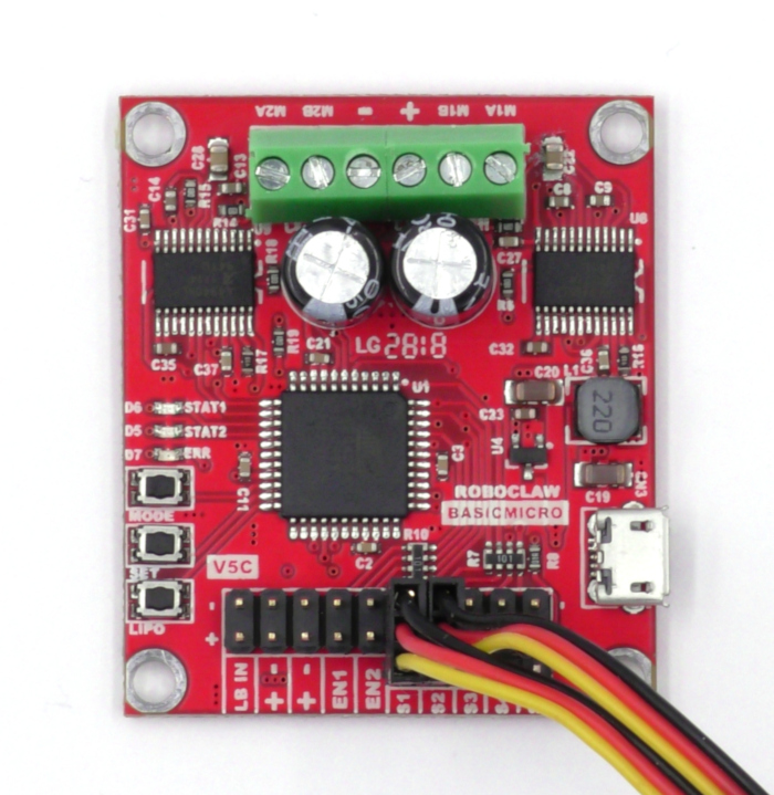
(1) Roboclaw with pin headers
(2) motors
(1) power supply
(1) RC transmitter
(1) RC receiver
(2-3) female to female servo cables
(1) power switch (optional)
(1) fuse (optional)
(1) 1-3A power diode (optional)
(1) micro USB cable
(1) computer running Microsoft Windows 7, 8 or 10
RC Receiver Types
There are three distinct types of receivers on the market: air, surface and marine receivers. There are also two general frequency bands in use for receivers: FM and 2.4GHz spread spectrum. The radio and receiver must operate on the same frequency band. Furthermore the radio and receiver type should be paired, surface radios with surface receivers and air receivers with air radios. Generally any type of radio and receiver combination can be used for combat robots but air radios and receivers offer the most flexibility for use with combat robots. The control scheme is more flexible with an air radio and air receivers often feature programmable failsafe options that are useful for combat robots.
Control Schemes
There are two control schemes that are commonly used to control combat robots: the dual stick setup (tank drive) and the single stick setup (arcade drive). The choice of control scheme determines how the receiver is wired to the RoboClaw.
Single Stick (Arcade Drive)
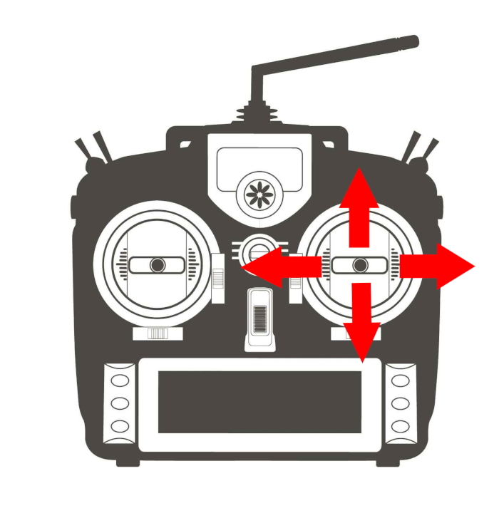
In a single stick configuration forwards and backwards movements are carried out by moving a single stick up or down. To turn the same stick is moved either left or right. The single stick configuration makes it easy to mix forwards and backwards motion with turning at the same time. Generally the right stick should be used for a single stick setup because on most radios this stick will return to center when released.
Figure 2: Single stick control scheme.
Dual Stick (Tank Drive)
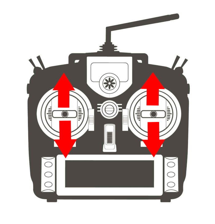
The dual stick setup ties one motor to each controls stick. Moving forwards or backwards is carried out by moving both stick forwards or backwards at the same time. To turn a robot with a dual stick configuration each stick is moved in opposite directions.
Figure 3: Twin stick control scheme.
Powering the Receiver (BEC/No BEC) and Receiver Installation
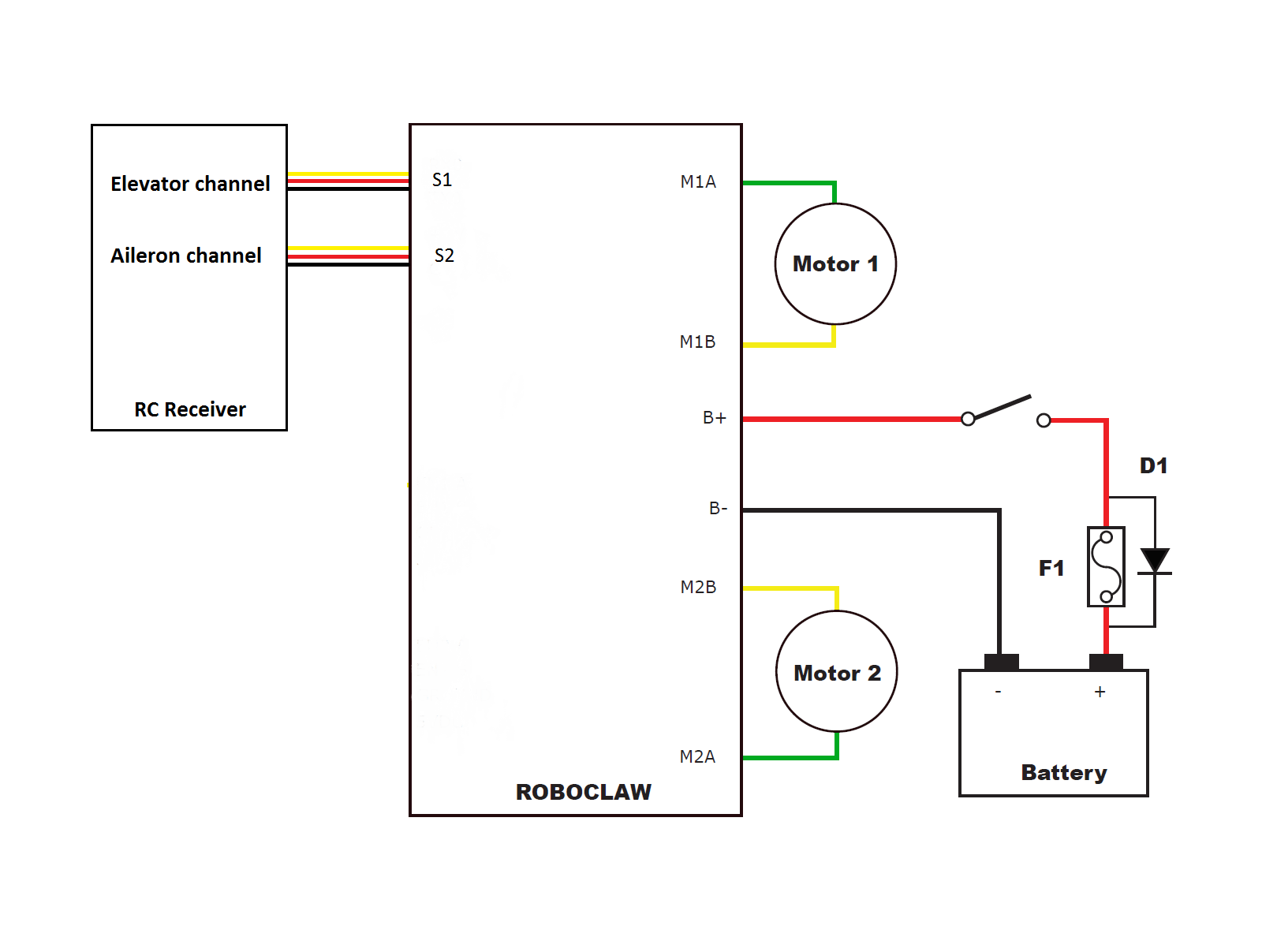
The RC receiver can be powered directly from the RoboClaw or from a secondary battery pack. When powering the RC receiver from the RoboClaw the receiver will be supplied with 5VDC from the center wire of the 3 pin servo cable. This system is known as a BEC (battery elimination circuit). The benefit of this scheme is a reduction in the complexity of the wiring. The downside to using the BEC is that a low main battery condition or a sudden power dip can cause a brownout condition that will cause the RoboClaw and receive to behave erratically. If the main battery will be run low or the motors of the robot will draw a large amount of current a secondary battery for the receiver is recommended. The wiring diagrams below show the wiring for using the BEC as well as using a receiver battery for both control schemes.
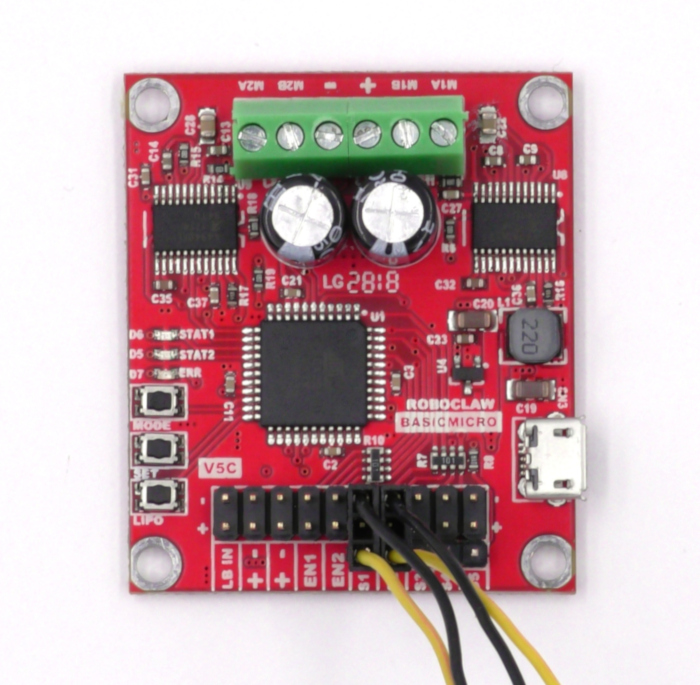
Follow the wiring diagrams below to wire the receiver to the RoboClaw. Wiring using the RoboClaw’s BEC uses a standard 3 wire servo cable, when using an external battery for the receiver the middle wire on the servo cables will need to be removed. Pay attention to the connections between the appropriate receiver channels and the S1/S2 headers of the RoboClaw. The S1 and S2 header pins are labeled with polarity markings.
RoboClaw BEC Powering the Receiver
Single Stick (Arcade Drive)
Figure 4: In this wiring configuration the 5V line is connected between the RoboClaw and receiver. The RobClaw powers the receiver.
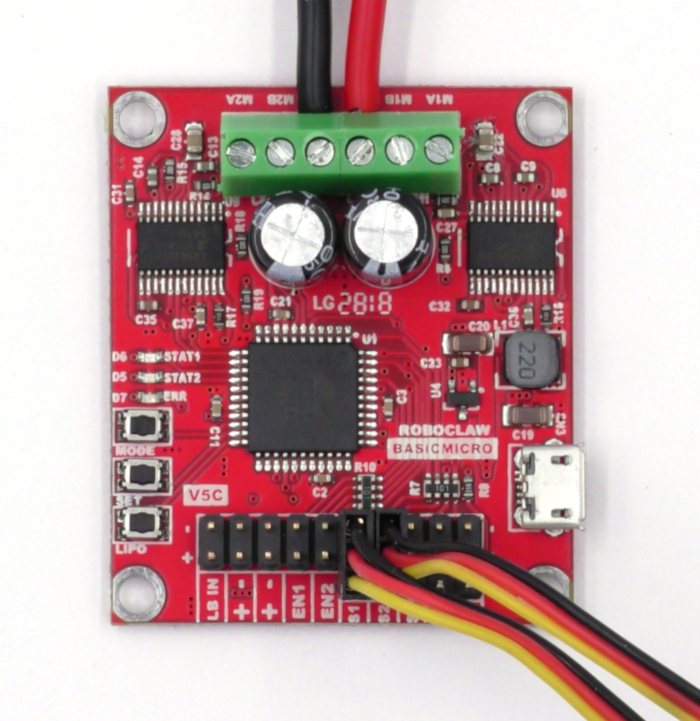
Dual Stick (Tank Drive)
Figure 5: In this wiring configuration the 5V line is connected between the RoboClaw and receiver. The RobClaw powers the receiver.
Figure 6: Two RC channels connected to the RoboClaw.
Receiver with External Power
Single Stick (Arcade Drive)
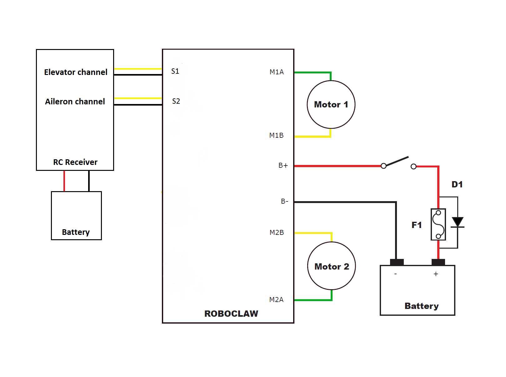
Figure 7: In this wiring configuration the receiver is powered externally and the 5V line between the RobClaw and receiver has been removed.
Dual Stick (Tank Drive)
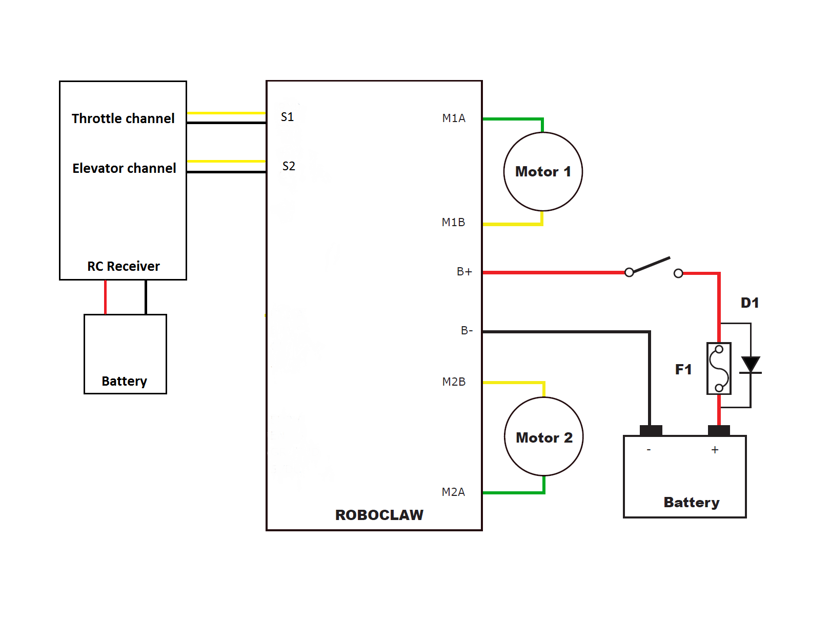
Figure 8: In this wiring configuration the receiver is powered externally and the 5V line between the RobClaw and receiver has been removed.
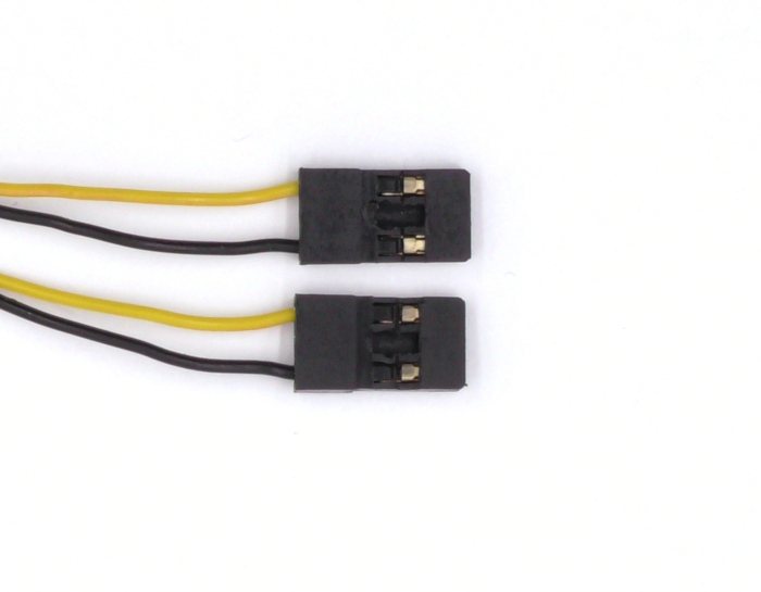
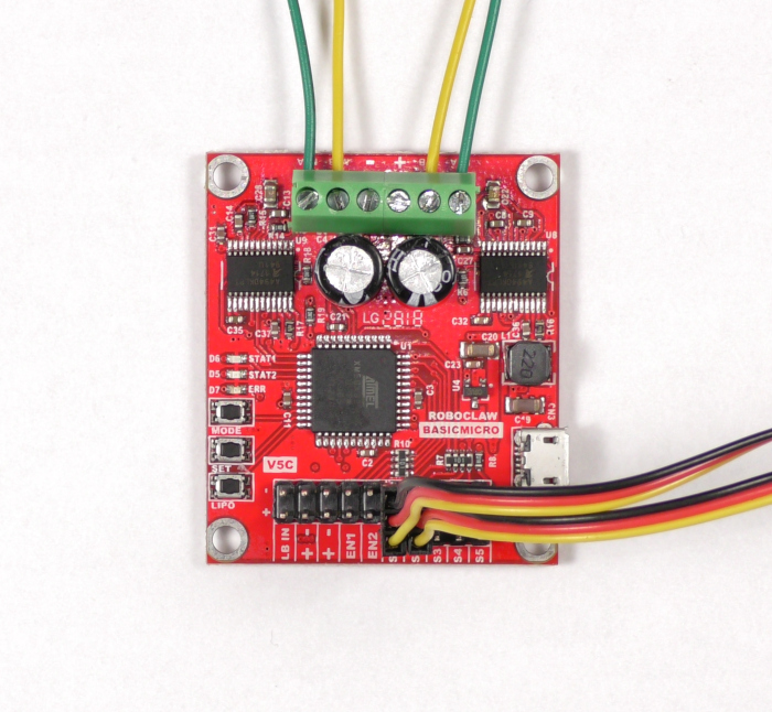
Figure 9: A servo cable altered to remove the 5V line when using an external BEC or battery.
Figure 10: Two RC channels connected to the RoboClaw with modified servo cables.
RoboClaw Hardware Installation and Verification
1. Install Basicmicro Motion Studio on the computer. Please see the tutorial here. Note that Basicmicro Motion Studio requires Windows 7 or later.
2. Identify the positive and negative leads of the battery. There are two screw terminals on the RoboClaw labeled + and -. Find these terminals and loosen the screws on them. Attached the negative lead first by placing the lead in the loosened terminal and tightening the screw down until the connection is snug. Repeat this step with the positive lead.
Figure 11: Power wired properly to the RobClaw.
3. Connect the USB cable between the RoboClaw and your computer.
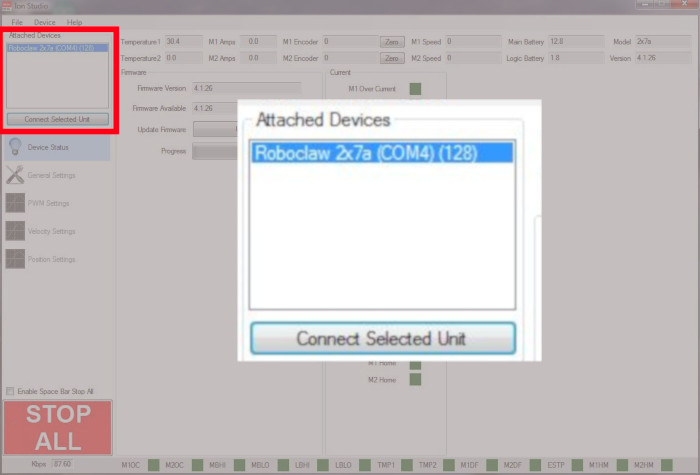
4. Open Basicmicro Motion Studio. In the upper left hand corner of the application you should see a box labeled “Attached Devices”. Your RoboClaw should appear here, if not check your USB connection and check that power has been properly applied to the RoboClaw. If your device is listed, select it and click “Connect Selected Unit”. The Stat1 led on the RoboClaw will begin flashing.
While Motion Studio is open check to see if the RoboClaw’s firmware needs to be updated. Follow the section named “Updating Firmware” in this Application Note to update the firmware.
Once you’ve verified that you can connect the RoboClaw to Motion Studio click “Disconnect Selected Unit” to stop communication with the RoboClaw.
Figure 12: The location in Motion Studio where a RoboClaw is connected.
5. Disconnect power from the RoboClaw by removing the positive lead and then the negative lead. You must do it in this order or you will damage the RoboClaw. If your battery has a switch you can simply open the switch to disconnect power.
6. It is recommended, but optional, to install a fuse and bypass diode in the power wiring harness. See this Application Note for details of how to do so. The wiring diagrams below show a fuse and bypass diode installed on the power wiring harness along with a power switch.
7. Now we will begin wiring the motors to the RoboClaw. Locate the terminals labeled M1A and M1B. Loosen the screws on these terminals before you begin wiring. Wire the first motor to the terminals labeled M1A and M1B by placing one end of the bare wire in each terminal and tightening the screws with your screwdriver until the connection is snug. Note that the order of wiring does not matter for the first motor.
8. The second motor is wired to the terminals labeled M2A and M2B. The order of wiring does matter for this motor. Look at the first motor you wired and note what color wire you wired to the M1A terminal. Connect the same colored wire of the second motor to the M2A terminal. Lastly, connect the final wire of the second motor to the M2B terminal. Make sure that your motor wire connections are secure and do not come loose from the terminals.
Figure 13: Two motors wired to the RoboClaw properly.
Note: An additional logic battery can be used to power the RoboClaw’s internal logic. This option is a good choice if the robot’s motors will likely draw large amounts of current. Large current spikes can temporarily lower the main battery voltage low enough to cause the RoboClaw to brown out. A logic battery is attached to the pin header labeled “LB IN”. During operation the RoboClaw will automatically select the power source to use so their is no further configuration needed to use this feature.
9. Reconnect power to the RoboClaw as done earlier.
10. Open Basicmicro Motion Studio again and reconnect the RoboClaw again by clicking “Connect Selected Unit”. Click on “PWM Settings” in the left-hand pane. Here we will test the motors to make sure they’re working. Find the box labeled “Control”. Slide the sliders for Motor 1 and Motor 2. The motors should turn when operating the sliders. Also check to ensure that the motors turn forwards when sliding the sliders up and backwards when sliding the sliders down. If the motors do not turn the proper direction you need to reverse the wiring of one or both motors.
Configuring RC Mode and Settings in Motion Studio
1. Ensure that power is still connected to the RoboClaw. Open Motion Studio once again and connect the RoboClaw in the application. On the left-hand side of the application click “General Settings”. This is where the RC mode and options will be configured.
Mode
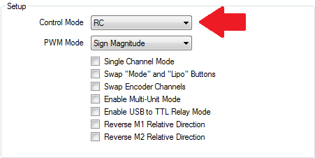
In the pane labeled “Setup” set the Control Mode to RC. This is the one setting that must be set for all control schemes and wiring configurations.
Figure 14: The control mode setting in Motion Studio.
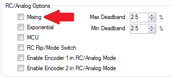
Mixing
The setting enables mixing two control channels together. Only enable this setting for the single stick control scheme, the dual stick control scheme does not use this setting.
Figure 15: The mixing setting in Motion Studio.
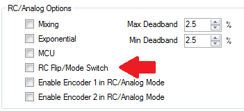
Flip Switch
This option allows a third control channel to reverse the controls if the robot is flipped over. Check the checkbox to enable it. A servo cable must be wired between the desired channel on the receiver and the S3 header to make this work.
Figure 16: The flip switch setting in Motion Studio.
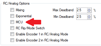
MCU mode
If the a logic battery has been attached or the robot is unlikely to experience brownouts click the checkbox labeled “MCU”. However if the robot is likely to experience brownouts or the receiver in use has failsafes against signal loss leave this box unchecked.
Figure 17: The MCU mode setting in Motion Studio.
Note: The primary difference between leaving MCU mode disabled and enabling it is the autocalibration feature. When MCU mode is disabled (default setting) RoboClaw uses the radio’s stick position at startup as the center of the range of motion. Autocalibration will also adjust the minimum and maximum endpoints if they deviate from the pre-programmed values. When MCU mode is enabled none of these adjustments occur and the center position as well as endpoints are determined by preset values.
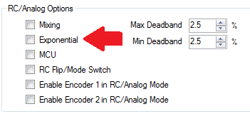
Exponential
This setting dampens the robots response around the center of the radio’s travel range. It can make a robot easier to control and less touchy in it’s response to moving the radio’s sticks.
Figure 18: The exponential setting in Motion Studio.
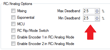
Deadband
This setting sets the range of stick travel from the center for which there is no motor response. Small stick motions around the center of the stick’s range will result in no movement of the robot. The value is set to a default value of 2.5% but can be customized to any value this is appropriate.
Figure 19: The deadband setting in Motion Studio.
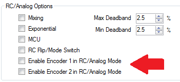
Encoders
When this option is selected the RoboClaw will use attached encoders to maintain velocity or position depending on what tuning has been configured. See this Application Note for details on how to tune a RoboClaw for velocity or position control.
Figure 20: Location in Motion Studio to enable encoders in RC mode.
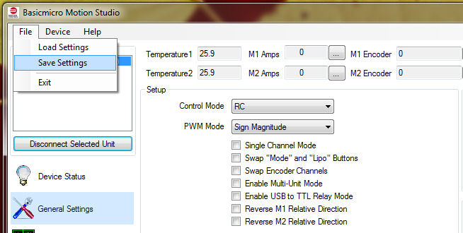
2. For future use the configuration should be saved to a file. See this Application Note for instructions on how to do this. Several ready to use RC mode configuration files can be found here. They can be loaded on to the RoboClaw by following this Application Note.
Figure 21: The menu location in Motion Studio where settings are saved to a file.
3. Once the settings have been saved click “Disconnect Selected Unit” in the upper left-hand side of the application to disconnect the RoboClaw from Motion Studio.
4. Disconnect the USB cable from the RoboClaw.
Settings Overview
The settings below are a quick reference of the settings and connections that need to be made for each control scheme.
Single Stick
Elevator channel on s1
Aileron channel on s2
RC mode enabled
Mixing enabled
MCU mode depending on chance of brownouts or presence of logic battery
Flip switch if reversing controls is needed
Dual Stick
Throttle channel on s1
Elevator channel on s2
RC mode enabled
Mixing disabled
MCU mode depending on chance of brownouts or presence of logic battery
Flip switch if reversing controls is needed
Testing
If the transmitter and receiver need to be bound do so before further testing. Disconnect power from the RoboClaw and the receiver if it’s being powered from an external battery. Turn the transmitter on and then re-power the RoboClaw. The RoboClaw should now respond to input from the transmitter by moving the motors in response to moving the appropriate sticks.
If things don’t work as expected there are a few things to check. First check that the servo cables connections are seated properly and are oriented correctly both at the receiver and at the RoboClaw. If using external power check to see if the battery is adequately charged and that the 5V line of the servo cables has been disconnected completely. Lastly, reconnect the RoboClaw to Motion Studio and ensure the settings listed previously are set and saved to the board.
Note: A loss of signal between the RC transmitter and receiver, either due to range or turning the transmitter off, can result in issues with the control of a robot. Many receiver will continue to send the last know stick positions to the RoboClaw. This can result in a robot running away or crashing. Some radio and receiver combinations can be programmed with failsafe positions to prevent these problems from occurring. Consult the documentation for the system being used for further details.